
Integrated programmable device for safety critical applications

a programmable device and application technology, applied in the field of integrated programmable devices for safety critical applications, can solve the problems of clear unsatisfactory plausibility checks for security critical applications, and achieve the effect of convenient integration and improvement of safety

Active Publication Date: 2006-05-25
TEXAS INSTR INC
View PDF4 Cites 3 Cited by
  • Summary
  • Abstract
  • Description
  • Claims
  • Application Information

AI Technical Summary

Benefits of technology

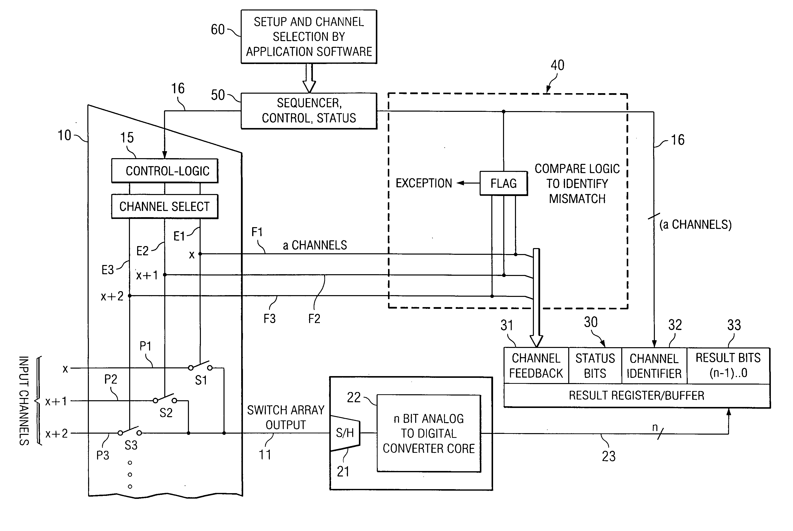
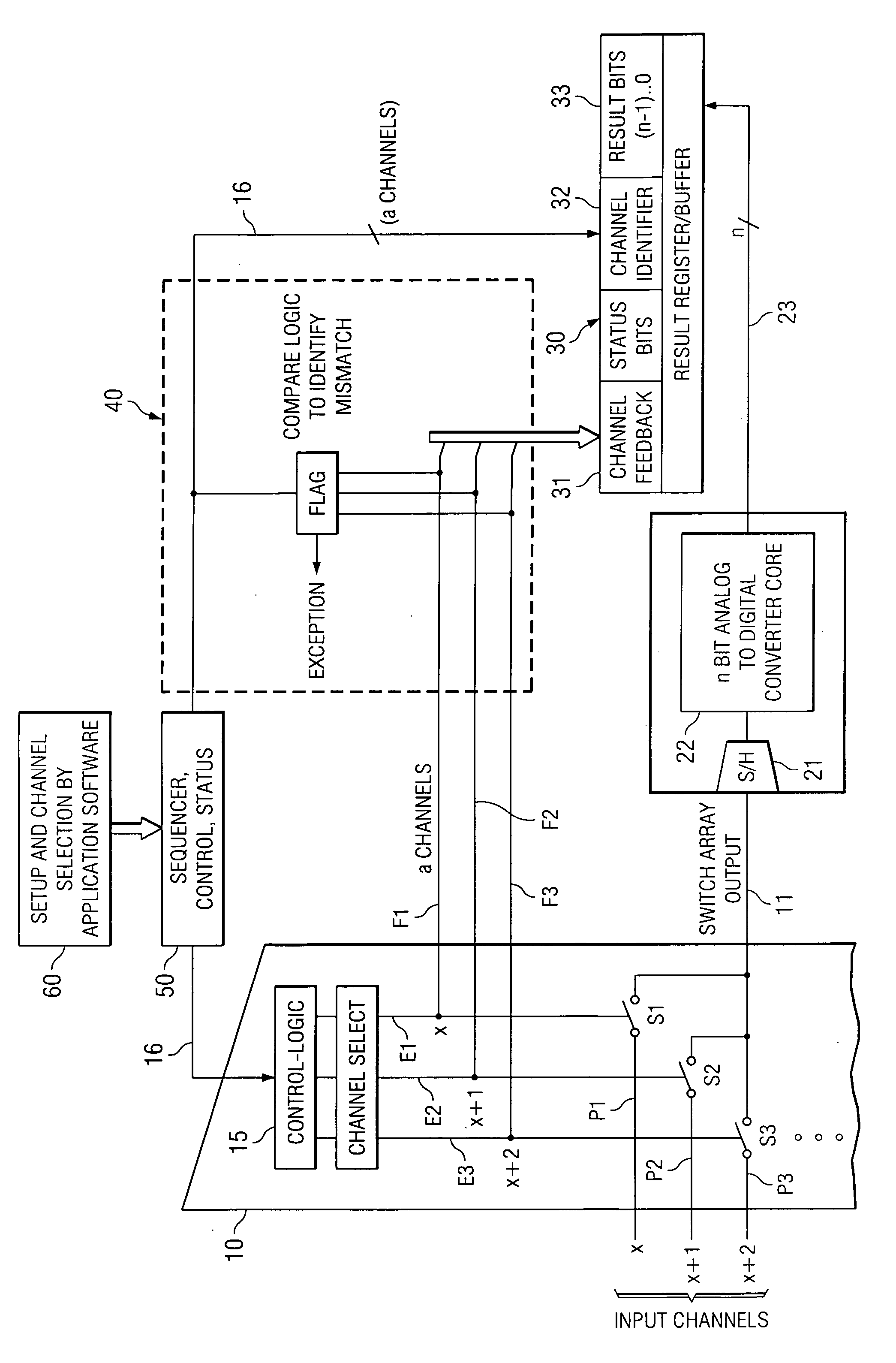
The invention is a programmable device that has a plurality of signal inputs connected to a plurality of switching elements. Each switching element has an associated enable line and a feedback line. A control circuit activates selected signal inputs via the enable lines in response to a channel select signal. The feedback lines provide feedback indicating which signal inputs have been enabled. The invention includes a compare logic circuit or a dedicated register or memory area that performs the comparison between the channel select signal and the channel feedback. The invention improves safety for programmable devices that have selectively connected analog inputs. It is easy to integrate into existing systems, does not require any external signals, components, or massive software overhead.

Problems solved by technology

Malfunctions of the related switch control logic would result in passing other than the specified input signals through the switch array.
Hardware and software designers are today faced with the problem of how to verify that the output of the switch array or multiplexer actually corresponds to the selected input channel.
Plausibility checks are clearly unsatisfactory for security critical applications.

Method used


Image

  • Integrated programmable device for safety critical applications
  • Integrated programmable device for safety critical applications

Examples


Embodiment Construction

[0010] The circuit shown in FIG. 1 has three analog signal inputs P1, P2 and P3. Each signal input is connected to an input terminal of a corresponding one of three switching elements S1, S2, and S3 of switch array 10. Each switching element S1 to S3 has an associated enable line E1, E2 and E3, which is connected to a logic control circuit 15 of the switch array 10. An input of control circuit 15 is connected via an n-bit parallel line 16 to control and status sequencer 50. Control and status sequenced 50 is controlled by application software 60. The three switch elements S1 to S3 have corresponding output terminals connected to output 11 of switch array 10. Output 11 is connected to an input of sample and hold circuit 21. The output of sample and hold circuit 21 feeds analog to digital (A / D) converter 22. An n-bit parallel line 23 leads from the digital output of A / D converter 22 to result bits memory area 33 of result register 30.

[0011] Each of enable lines E1 to E3 is connected ...


PUM


Abstract

An integrated programmable device has a plurality of signal inputs (P1, P2, P3) connected to respective ones of a plurality of switching elements (S1, S2, S3). Each switching element (S1, S2, S3) has an associated enable line (E1, E2, E3). A control circuit (15) activates one or more selected signal inputs (P1-P3) in accordance with a channel select signal (16) via these enable lines (E1, E2, E3). Feedback lines (F1, F2, F3) are connected to corresponding enable lines (E1, E2, E3) to a channel feedback indicative of which signal inputs (P1, P2, P3) is enabled. This allows determination whether the enabled signal inputs (P1, P2, P3) correspond to the channel select signal (16) and initiates an exception handling in case of a mismatch. The comparison can be performed by a compare logic circuit (40) or the channel feedback can be stored in a memory (30) accessible by a software program (60), which performs the comparison.

Description

BACKGROUND OF THE INVENTION [0001] In automotive applications, more and more functions are implemented by programmable devices and associated application software rather than by dedicated circuitry. This is true for safety critical applications such as Electronic Stability Program (ESP) or airbag control and release. Proper operation is absolutely mandatory for such safety critical functions. Thus the programmable device and its associated application software must always operate properly. [0002] Programmable devices are naturally used in common for several different applications. Switch arrays or multiplexers are used to selectively feed different input signals to the programmable device for the corresponding applications. It is mandatory for safety critical applications to ensure that the right input signals are selected by the switch array or multiplexer and fed to the programmable device. Malfunctions of the related switch control logic would result in passing other than the spe...

Claims


Application Information

Patent Timeline
Patent Type & Authority Applications(United States)
IPC IPC(8): H04L12/50
CPCG05B19/0428G05B2219/24196
Inventor WAGNER, RALFFUESSL, BERNHARDKREUTZER, ARTHUR
Owner TEXAS INSTR INC
Learn More