Mobile communication receiver and transmitter

Inactive Publication Date: 2006-05-25
NTT DOCOMO INC
View PDF3 Cites 119 Cited by
  • Summary
  • Abstract
  • Description
  • Claims
  • Application Information

AI Technical Summary

Benefits of technology

[0009] The present invention was conceived to overcome the above-described problems in the prior art, and aims to provide a signal transmission and receiving technique in mobile communication that allows wir

Problems solved by technology

With this technique, however, when starting communication with other wireless equipment, the currently applied mobile communication system has to be informed at the receiver using a control signal, and accordingly, the transmission efficiency is inevitably degraded.
However, it appears to be difficult to share the control signals among different users or different systems sharing the same frequency band.
Accordingly, it is not a practical idea to apply control signals to allow the receiver to distinguish between multiple wireless schemes used by different users.
However, in reality, various types of wireless schemes exist because of sophistication and diversification of mobile com

Method used


Image

  • Mobile communication receiver and transmitter
  • Mobile communication receiver and transmitter
  • Mobile communication receiver and transmitter

Examples


first embodiment

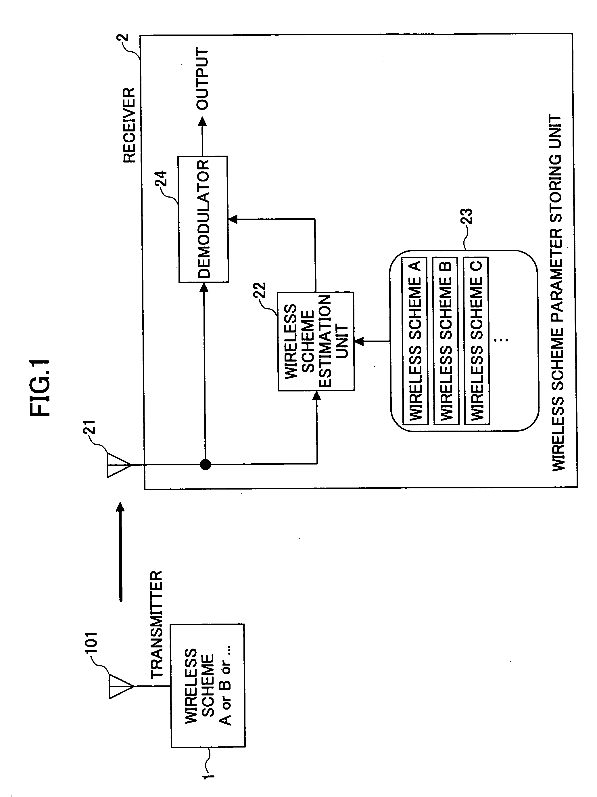
[0041]FIG. 1 is a schematic diagram illustrating examples of a transmitter 1 and a receiver 2 according to the first embodiment of the invention. The transmitter 1 has an antenna 101, and it selects an appropriate wireless scheme from multiple wireless schemes (A, B, and some more) to transmit a signal. The receiver 2 has an antenna 21, a wireless scheme estimation unit 22 for estimating the wireless scheme based on the signal received at the antenna 21, a wireless scheme parameter storing unit 23 for storing wireless parameters for each of the wireless schemes (A, B, . . . ), and a demodulator 24 for demodulating the received signal based on the estimated wireless scheme.

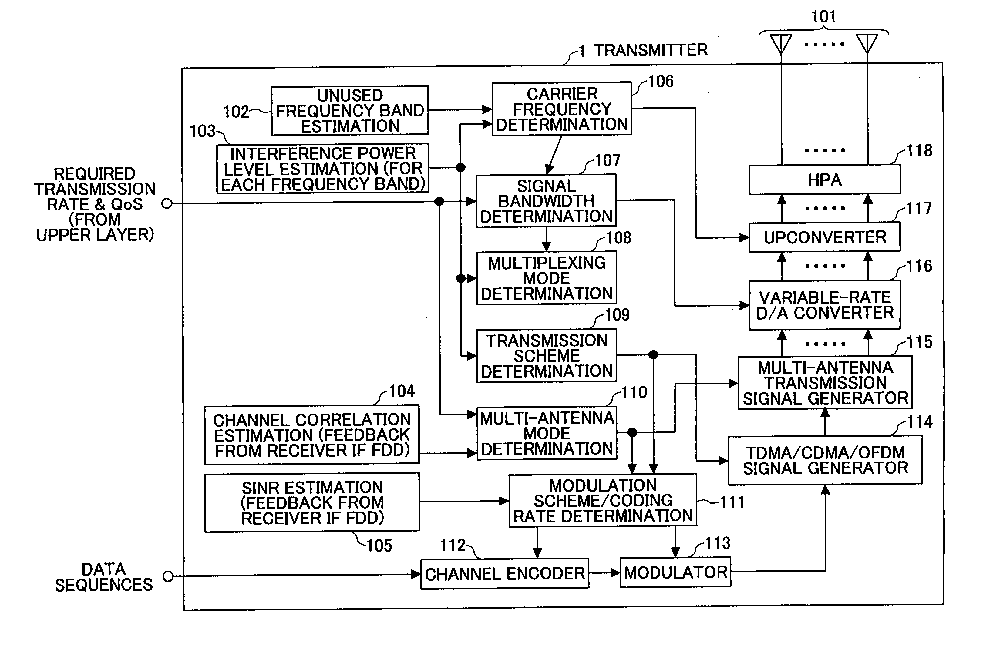
[0042] The transmitter 1 changes the wireless schemes according to the currently required transmission rate, quality of services (QoS) including channel quality, and the propagation environment. The parameters defining the wireless schemes includes:

(1) center carrier frequency;

(2) signal bandwidth;

(3) multip...

second embodiment

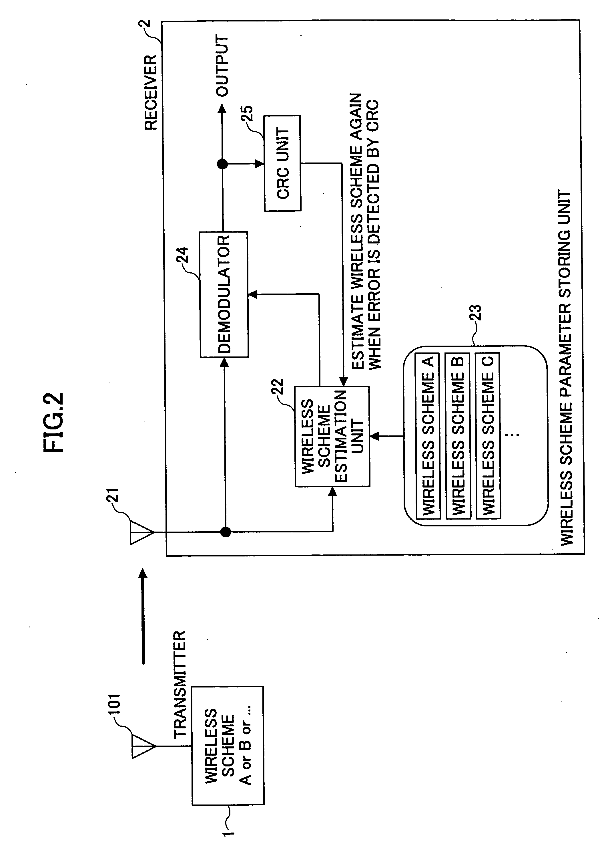
[0054]FIG. 2 is a schematic diagram illustrating a transmitter 1 and a receiver 2 according to the second embodiment of the invention. In this embodiment, a CRC unit 25 is added to the receiver 2 to detect an error in demodulation result by cyclic redundancy check.

[0055] Similar to the first embodiment, the wireless scheme estimation unit 22 of the receiver 2 estimates the currently used parameters of the wireless schemes by selecting the parameters most likely to be used by the transmitter 1 for the respective wireless schemes from the wireless scheme parameter storing unit 23. The demodulator 24 demodulates the received data based on the selected wireless schemes. Then, the CRC unit 25 checks whether the demodulated data contain any error. If an error is detected, the wireless scheme estimation unit 22 estimates a set of wireless schemes again. To be more precise, the second most likely wireless parameter set, other than the previously selected one, is selected from the wireless ...

third embodiment

[0056]FIG. 3 is a schematic diagram illustrating transmitters 1 and a receiver 2 according to the third embodiment of the invention. In the third embodiment, a second wireless scheme estimation unit (an interference signal wireless scheme estimation unit) 22b is added to the structure shown in FIG. 1 to estimate the wireless transmission scheme of an interfering transmitter 1b. An interference canceller 26 is also added to cancel the interference signal from the received signal. The first wireless scheme estimation unit 22a that estimates the wireless schemes currently used by the target transmitter 1a corresponds to the wireless scheme estimation unit 22 shown in FIG. 1, and the desired signal demodulator 24a corresponds to the demodulator 24 shown in FIG. 1.

[0057] In operation, the first wireless scheme estimation unit 22a estimates the wireless schemes selected by the target transmitter 1a based on the received signal. The second wireless scheme estimation unit 22b estimates the...


PUM


Abstract

A receiver for mobile communication includes a wireless scheme parameter storing unit (23) configured to store a plurality of characteristics of multiple wireless schemes, a wireless scheme estimation unit (22) configured to estimate one of the characteristics of a currently used wireless scheme from a received signal and select one of the wireless schemes corresponding to the estimated characteristic from the wireless scheme parameter storing unit, and a demodulator (24) configured to demodulate the received signal based on the selected wireless scheme.

Description

FIELD OF THE INVENTION [0001] The present invention generally relates to a mobile communication technique, including mobile communication receivers and transmitters, and more particularly to a technique for efficiently and adaptively changing parameters of wireless schemes in accordance with the radio environment and required conditions including quality of services. BACKGROUND OF THE INVENITON [0002] Conventionally, wireless parameters, including a transmission scheme (e.g., time division multiple access (TDMA) or code division multiple access (CDMA)), a carrier frequency band, and a signal bandwidth, are defined system by system, such as a parameter set for a personal digital cellular (PDC) telecommunication system or a parameter set for a wireless LAN. Transmitters and receivers perform wireless communications based on the wireless parameters fixed in an inflexible manner. Accordingly, a user with PDC equipment, for instance, cannot communicate with other PDC equipment unless an ...

Claims


Application Information

Patent Timeline
IPC IPC(8): H04B7/06H04B7/10H04B7/04H04B7/26H04J1/00H04J11/00H04J13/00H04J99/00H04W76/00H04W88/02H04W88/06
CPCH04B1/0003H04L1/0003H04L1/0009H04L1/0015H04L25/03006H04L27/0012
Inventor ASAI, TAKAHIROABE, TETSUSHIYOSHINO, HITOSHI
Owner NTT DOCOMO INC
Why Eureka
Try Eureka