Sound projector

a sound projector and projector technology, applied in the direction of transducer details, magnetic restriction transducers, instruments, etc., can solve the problems of moisture penetrating the transmission/reception unit, the reflective face is soiled, and the audio signal is now audible, so as to achieve high-directional sound

Inactive Publication Date: 2006-05-25
DAIMLER AG
View PDF2 Cites 28 Cited by
  • Summary
  • Abstract
  • Description
  • Claims
  • Application Information

AI Technical Summary

Benefits of technology

[0011] The novel directional loudspeaker comprises a sound source for producing highly directional sound which is formed by at least one ultrasound loudspeaker. There is also a pivotable reflector for deflecting the directional sound. Inventively, the reflector is now designed such that it can be pivoted such that its serves as mechanical protection for the directional loudspeaker's sound source. This protection is particularly against environmental influences such as soiling and moisture. In...

Problems solved by technology

This nonlinearity results in demodulation of the audio signal which is now becoming audible.
Since the total arrangement is not surrounded by a housing, there is ...

Method used


Image

  • Sound projector
  • Sound projector
  • Sound projector

Examples


Embodiment Construction

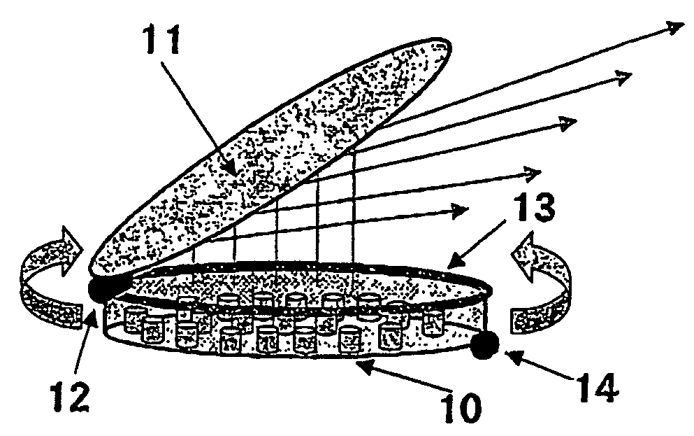
[0023] In particularly profitable fashion, the directional loudspeaker's sound source is installed in a housing which can be sealed with the correct fit by the reflector. To this end, the reflector is particularly advantageously connected to the housing by a moving connection, which results in a type of can in which the reflector forms the lid and which can be opened and closed by changing the orientation of the reflector. In this case, the choice of moving connection is essentially dependent on the demands on the desired degree of movement for the reflector. It is thus conceivable to use a simple hinge, or else, particularly to increase the degrees of movement for the reflector, to resort to ball-and-socket joints, universal joints or cardan joints.

[0024] In particularly profitable fashion, the housing in which the sound source is installed has an essentially circular cross section. This makes it possible, by way of example, to mount the pivot joint on a raceway which is seated on...


PUM


Abstract

Parametric loudspeakers that are based on a modulated ultrasound carrier signal produce strong directional patterns. This strong directional patterns require a direct transmission path from the loudspeaker to the audience. Obstacles in this path have a reflecting or absorbing effect. The invention describes a mechanical arrangement of a parametric loudspeaker with a mobile reflector. The arrangement allows tracking of the emitted sound in the direction of a moving audience. The invention provides for advantageous installation possibilities, for example in the rooflining of vehicles or as a mobile system.

Description

BACKGROUND OF THE INVENTION [0001] 1. Field of the Invention [0002] The invention relates to a directional loudspeaker and to a method which is suitable for operating such a directional loudspeaker in accordance with the precharacterizing parts of patent claims 1 and 13. [0003] 2. Related Art of the Invention [0004] Conventional systems in which the audio signal is radiated as an oscillation of air directly via single loudspeakers or else a loudspeaker array are able to achieve only relatively limited focusing of the radiated sound. By contrast, a novel method sends the audio signal not directly but rather as an alteration in the amplitude (amplitude modulation, AM) of a carrier oscillation at very high frequency (ultrasound). The underlying physical phenomenon of acoustic perception of sounds as a sequence of nonlinear properties of the air has already been recognized and examined by the physicists Helmholtz in the 19th century. The application of the physical principles for buildi...

Claims


Application Information

Patent Timeline
IPC IPC(8): H04R25/00G10K11/28H04R1/34H04R1/40
CPCG01N2291/02491G10K11/28H04R1/345H04R1/403H04R2217/03H04R2499/13
Inventor LINHARD, KLAUS
Owner DAIMLER AG
Why Eureka
Try Eureka