Torque transfer system and method of using the same

a technology of torque transfer and transmission system, which is applied in the direction of mechanical equipment, electrical equipment, dynamo-electric machines, etc., can solve the problems of increasing the cost and productivity loss of repairs, the maximum upper limit of the operational speed and the failure of the physically connected members in the early stages, so as to prevent the generation of heat and friction, prevent the transmission of shearing stresses, and prevent the effect of damage to the system

Inactive Publication Date: 2006-05-25
MAGNETIC TORQUE INT
View PDF98 Cites 40 Cited by
  • Summary
  • Abstract
  • Description
  • Claims
  • Application Information

AI Technical Summary

Benefits of technology

[0008] An object of the present invention is to provide a system and method for transferring rotational motion and torque that prevents generation of heat and friction.
[0009] Another object of the present invention is to provide a system and method for transferring rotational motion and torque that includes a method for preventing damage to the system.
[0010] Another object of the present invention is to provide a system and method for transferring rotational motion and torque that prevents transmission of shearing stresses.
[0011] Another object of the present invention is to provide a system and method for transferring rotational motion and torque that includes a method for preventing transmission of shearing stresses.

Problems solved by technology

However, due to mechanical friction between the physically connected members, significant amounts of heat are generated that causes premature failures of the physically connected members and increases costs and loss of productivity due to repairs.
Moreover, although the mechanical friction may be reduced by supplying a lubricant to the physically connected members, operational speed of the physically connected members has a maximum upper limit, thereby severely limiting transfer of the rotational motion between the first and second rotational shafts.
Thus, in the event that the maximum torque limit is achieved, the shear device must be replaced, thereby increasing costs and decreasing productivity.
Moreover, any misalignment of the first and second rotational shafts will result in a transfer of corresponding shearing stresses to the physically connected members.

Method used


Image

  • Torque transfer system and method of using the same
  • Torque transfer system and method of using the same
  • Torque transfer system and method of using the same

Examples


Embodiment Construction

[0022] Reference will now be made in detail to the preferred embodiments of the present invention, examples of which are illustrated in the accompanying drawings.

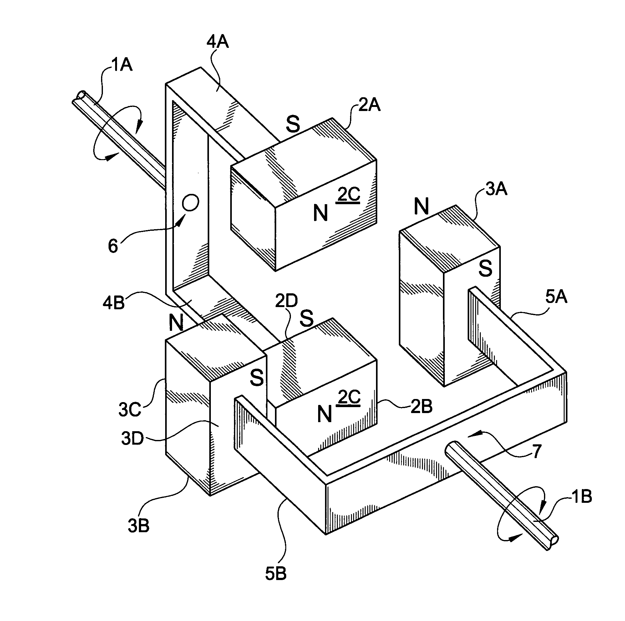
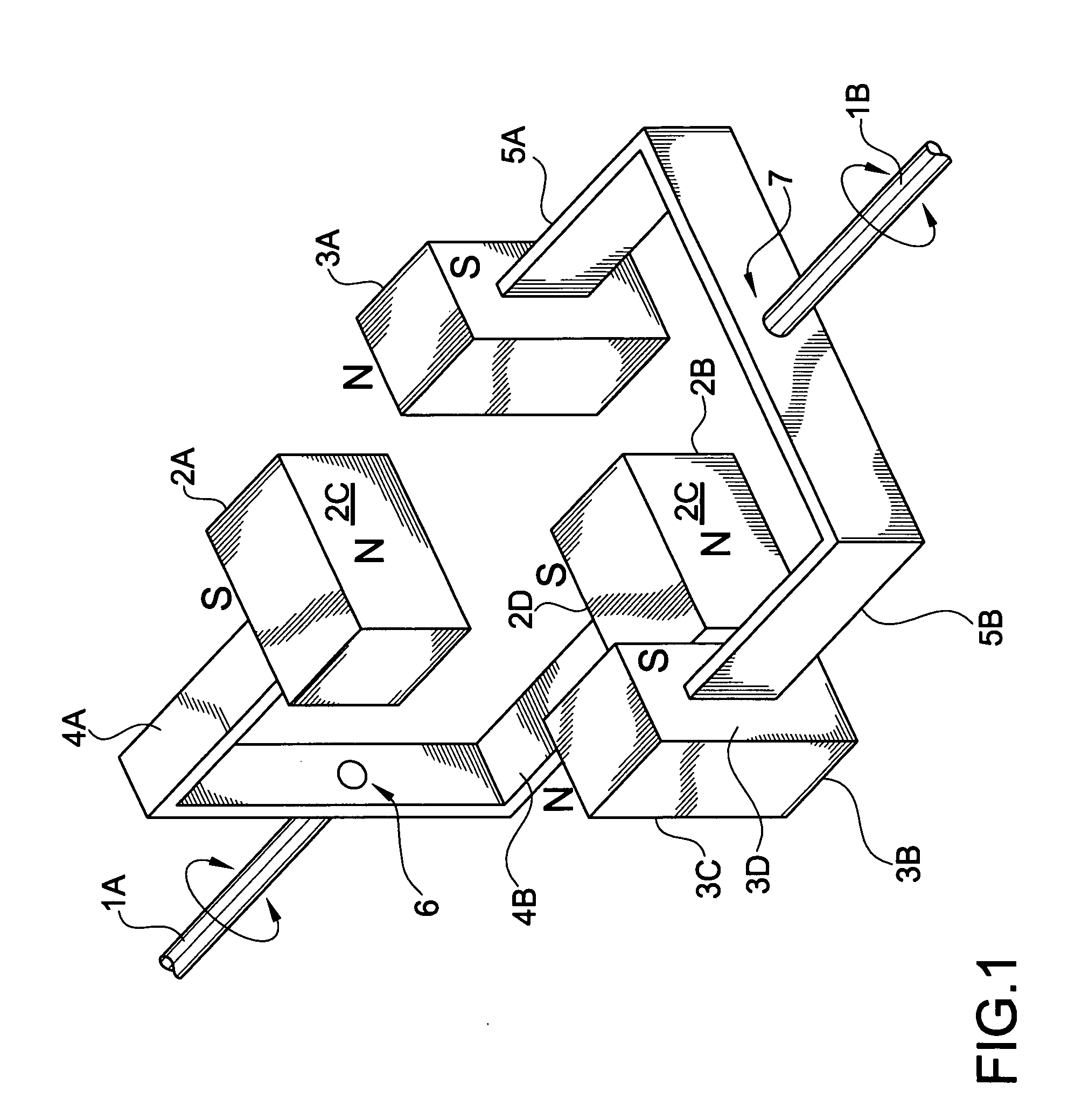
[0023]FIG. 1 is a perspective plan view of an exemplary torque transfer system according to the present invention. In FIG. 1, a torque transfer system may include a first rotational shaft 1A and a second rotational shaft 1B. Both the first and second rotational shafts 1A and 1B may be coupled to other devices that may make use of the rotational motion and torque transmitted by the first and second rotational shafts 1A and 1B. In addition, the first rotational shaft 1A may be coupled to a first pair of magnetic members 2A and 2B via first coupling arms 4A and 4B, respectively, using a shaft coupling 6. Similarly, the second rotational shaft 1B may be coupled to a second pair of magnetic members 3A and 3B via second coupling arms 5A and 5B, respectively, using a shaft coupling 7. Accordingly, the first pair of magnetic membe...


PUM


Abstract

A system for transferring rotational motion includes a first rotational shaft extending along a first axial direction, and a second rotational shaft disposed along a second axial direction and spaced apart from the first rotational shaft, wherein the first rotational shaft is magnetically coupled to the second rotational shaft.

Description

BACKGROUND OF THE INVENTION [0001] 1. Field of the Invention [0002] The present invention relates to a torque transfer system and a method of using a torque transfer system, and more particularly, to a system and a method for transferring torque between physically disconnected rotating shafts. [0003] 2. Discussion of the Related Art [0004] In general, transmission of rotational motion is accomplished by coupling rotating shafts using a combination of physically connected members. For example, in order to transfer rotational motion from a first rotational shaft to a second rotational shaft, either gears, belts, or chains are commonly used. However, due to mechanical friction between the physically connected members, significant amounts of heat are generated that causes premature failures of the physically connected members and increases costs and loss of productivity due to repairs. Moreover, although the mechanical friction may be reduced by supplying a lubricant to the physically c...

Claims


Application Information

Patent Timeline
Patent Type & Authority Applications(United States)
IPC IPC(8): H02N13/00
CPCH02K49/102Y10T464/30H02K49/108H02K49/10
Inventor WISE, RICHARD J.
Owner MAGNETIC TORQUE INT
Why Eureka
Try Eureka