Serpentine cutting blade for cutting balloon

a cutting blade and serpentine technology, applied in the field of serpentine cutting blades for cutting balloons, can solve the problems of limiting the ability of the blade to elongate, partial or even complete blockage of the artery, and stress therebetween

Active Publication Date: 2006-05-25
BOSTON SCI SCIMED INC
View PDF91 Cites 86 Cited by
  • Summary
  • Abstract
  • Description
  • Claims
  • Application Information

AI Technical Summary

Benefits of technology

[0016] The blade may be constructed of any material suitable for forming a cutting blade. The body region of the blade defines at least one cutting surface or edge. Regions of the blade adjacent to the body region need not include a cutting surface. As such, in at least one embodiment different regions of the blade define one or more different cross-sectional shapes. In at least one embodiment the body region of the blade defines a substantially triangular shaped cross-section. In at least one embodiment regions of the blade adjacent the body region have rectangular (ribbon), round, ovoid, square or other cross-sectional shape(s).
[0017] In at least one embodiment one or more portions of the blade in close proximity to the balloon surface are engaged to the balloon surface by an adhesive or other mounting material. The adhesive may be any adhesive material suitable for securing a metal, polymer or carbon based blade to the material of the balloon.
[00

Problems solved by technology

This can result in a partial, or even complete, blockage of the artery.
The rigid axial structure of the blade naturally limits the blades ability to elongate with the underlying balloon material during balloon expansion at high pressure.
As a result, stress between the comparatively axially rig

Method used


Image

  • Serpentine cutting blade for cutting balloon
  • Serpentine cutting blade for cutting balloon
  • Serpentine cutting blade for cutting balloon

Examples


Embodiment Construction

[0030] While this invention may be embodied in many different forms, there are described in detail herein specific preferred embodiments of the invention. This description is an exemplification of the principles of the invention and is not intended to limit the invention to the particular embodiments illustrated.

[0031] For the purposes of this disclosure, like reference numerals in the figures shall refer to like features unless otherwise indicated.

[0032] As indicated above, the present invention is embodied in a variety of forms.

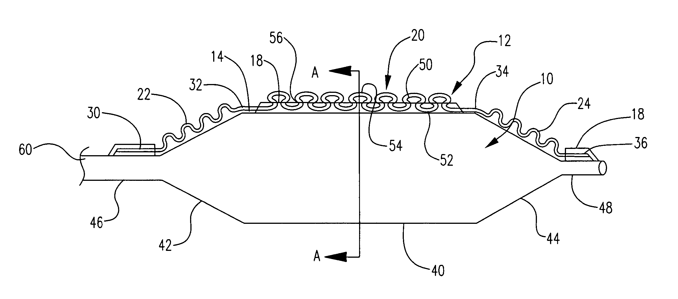
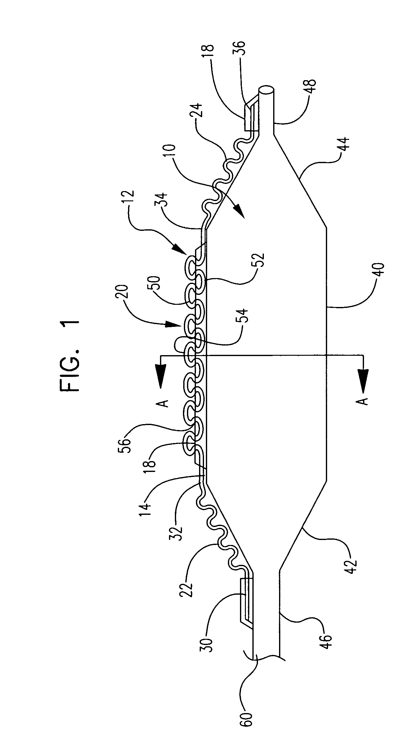
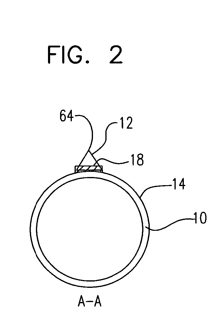
[0033] In at least one embodiment, an example of which is depicted inFIG. 1, the invention is directed to a catheter balloon 10 which has at least one serpentine, undulating, or similarly configured blade 12 mounted to the external surface 14 of the balloon. As shown, the blade 12 comprises at least one serpentine region 20. The majority or all of the blade may have a serpentine configuration, the blade may comprise a single serpentine region or any numb...


PUM


Abstract

A system for treatment of a vessel lesion comprises an expandable balloon and at least one cutting blade engaged to an exterior surface of the balloon. At least a portion of the cutting blade has a substantially serpentine configuration defined by a plurality of interconnected peaks and troughs wherein each trough is in closer proximity to the balloon than each peak.

Description

CROSS-REFERENCE TO RELATED APPLICATIONS [0001] Not Applicable STATEMENT REGARDING FEDERALLY SPONSORED RESEARCH [0002] Not Applicable BACKGROUND OF THE INVENTION [0003] Arterial blockages, which are also called stenosis, lesions, stenotic lesions, etc, are typically caused by the build-up of atherosclerotic plaque on the inside wall of an artery. In fact, several such stenoses may occur contiguously within a single artery. This can result in a partial, or even complete, blockage of the artery. As a result of the danger associated with such a blockage, several methods and procedures have been developed to treat stenoses. One such method is an angioplasty procedure which uses an inflatable balloon to dilate the blocked artery. A typical inflatable angioplasty device, for example, is disclosed in U.S. Pat. No. 4,896,669. [0004] Angioplasty balloons have enjoyed widespread acceptance in the treatment of stenoses. Recent studies, however, have indicated that the efficacy of the dilation o...

Claims


Application Information

Patent Timeline
IPC IPC(8): A61B17/22
CPCA61B17/320725A61B2017/22061
Inventor KELLEY, GREG S.
Owner BOSTON SCI SCIMED INC
Why Eureka
Try Eureka