Prosthetic venous valves

a technology of prosthetic venous valves and valves, applied in the field of medical arts, can solve the problems of affecting the quality of life of patients, venous hypertension, and degradation of the functionality of one or more venous valves, and achieve the effect of improving sealing

Inactive Publication Date: 2006-05-25
BIOMEDICAL RES ASSOCS +1
View PDF28 Cites 144 Cited by
  • Summary
  • Abstract
  • Description
  • Claims
  • Application Information

AI Technical Summary

Benefits of technology

[0012] According to one aspect, a prosthetic venous valve is disclosed. A frame includes: (i) a generally hollow base disposed at a blood inflow end; (ii) a plurality of struts connected with the base and extending generally parallel to a direction of forward flow of blood from the generally hollow base to a blood outflow end; and (iii) inwardly oriented flanges disposed at the blood outflow ends of the struts. Leaflets are disposed in gaps between the struts and are supported by the frame. The leaflets are arranged to close into the vein lumen to substantially seal against backflow of blood from the blood outflow end to the blood inflow end. The inwardly oriented flanges of the struts enhance the sealing.

Problems solved by technology

Chronic venous insufficiency is typically difficult to treat, often disabling, and negatively impacts the patient's quality of life.
The most common cause of venous hypertension is degradation of the functionality of one or more venous valves in the deep veins.
However, degraded venous valves are unable to completely block backflow of venous blood, resulting in development of venous hypertension and stasis.
The venous hypertension and stasis, in turn, leads to additional distention of the vein and further degradation of the valve.
Patients suffering from chronic venous insufficiency often also suffer from other vascular and / or coronary diseases, and so it may be undesirable to transplant healthy venous tissue that may be needed for later bypass procedures.
However, availability of suitably prepared animal vein valves, interspecies tissue compatibility, and other concerns arise in such procedures.
Such normally closed designs have been successful in the cardiac environment; however, they generally exhibit poor performance in the low flow, low pressure venous system that fosters thrombosis and intimal hyperplasia of implanted prosthetic devices.
Flow resistance caused by a normally closed or incompletely open venous valve replacement further increases blood residency time and can lead to blood clotting.
This in turn reduces the likelihood of blood clot formation at or near the venous valve replacement.

Method used


Image

  • Prosthetic venous valves
  • Prosthetic venous valves
  • Prosthetic venous valves

Examples


Embodiment Construction

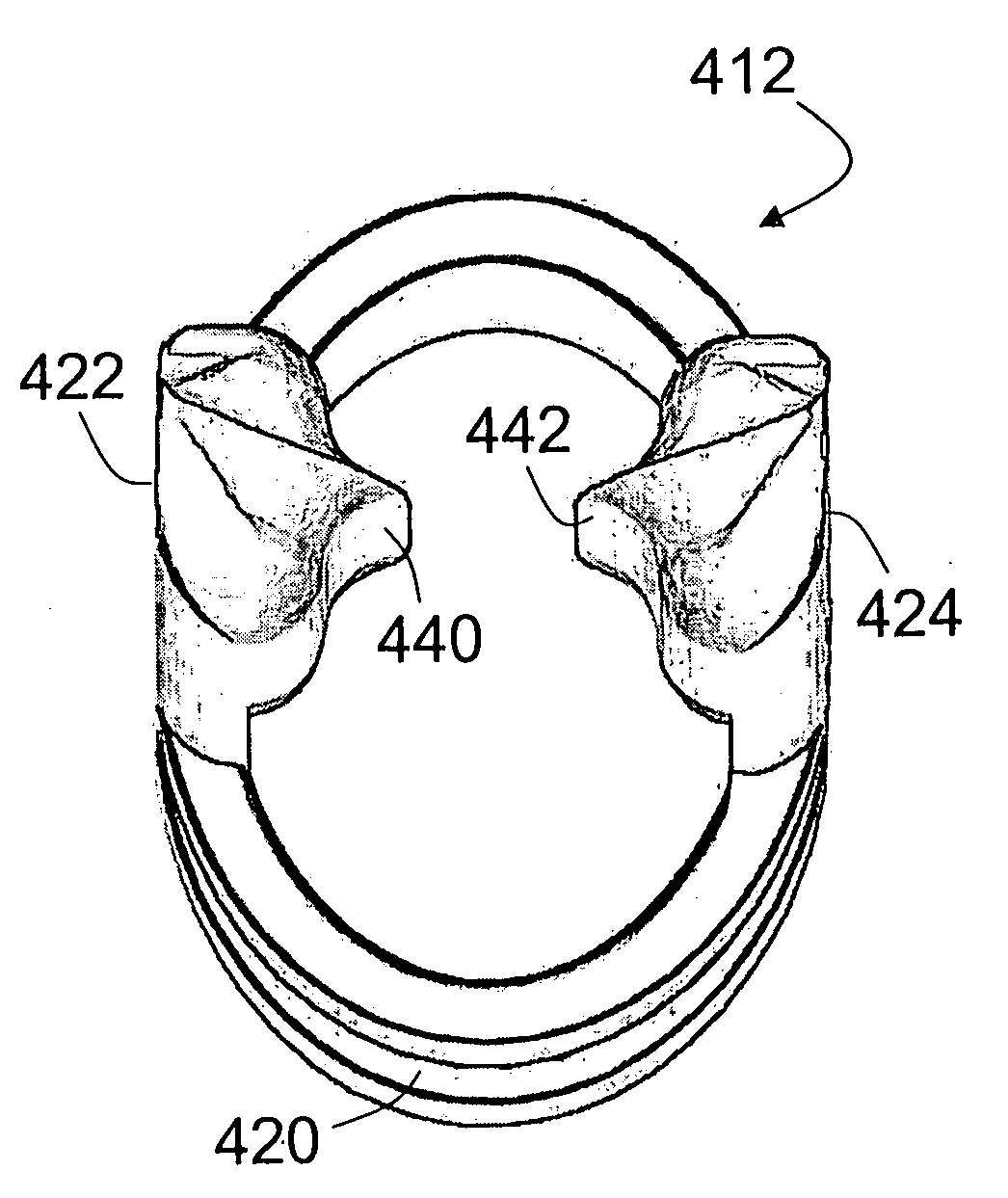
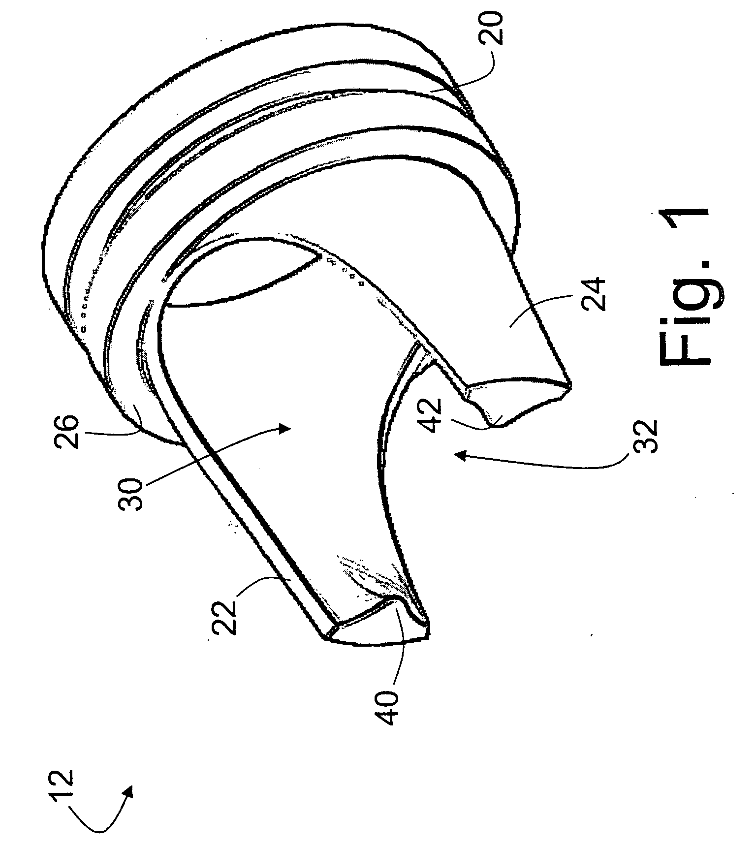
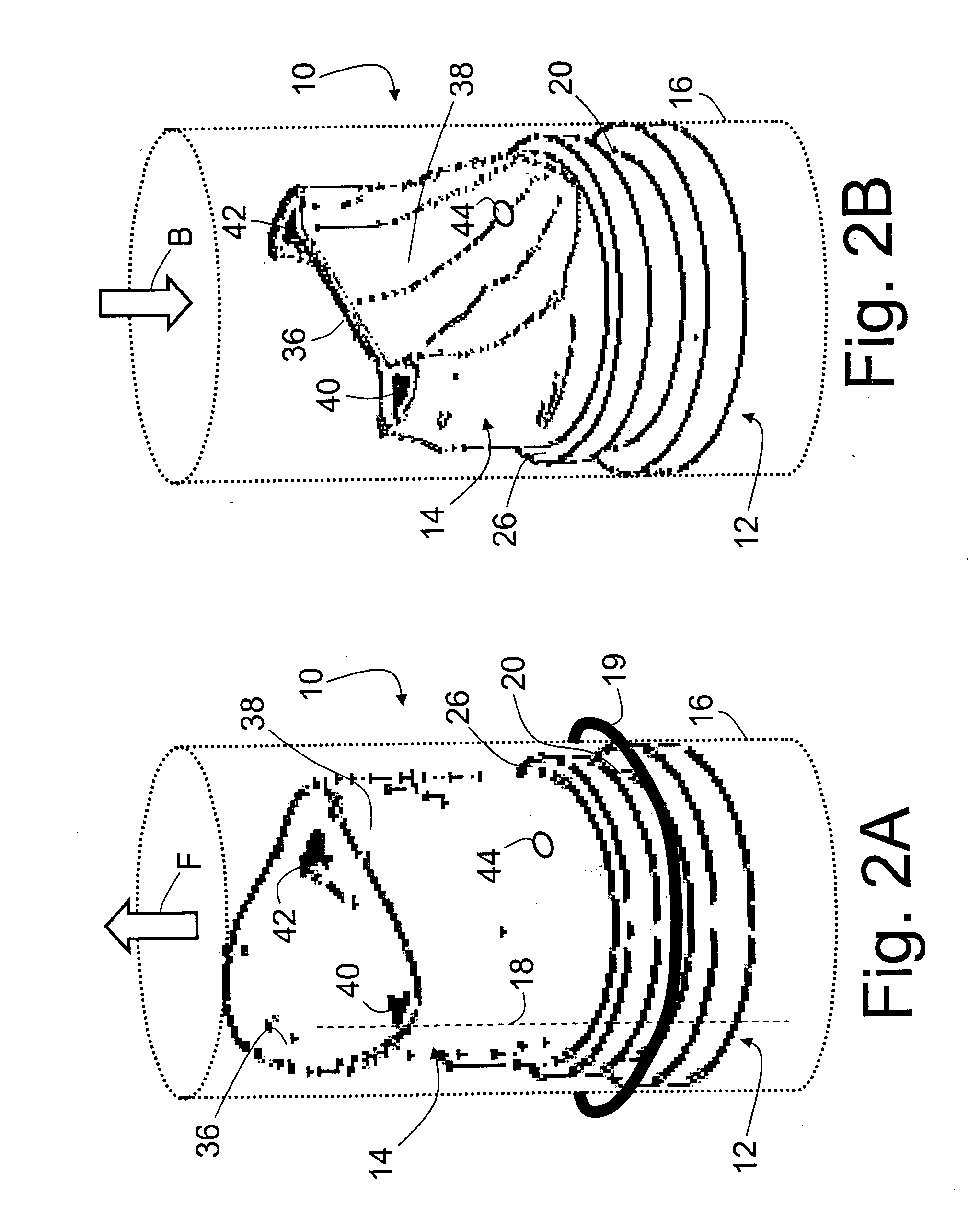
[0040] With reference to FIGS. 1, 2A, and 2B, a normally open prosthetic venous valve 10 includes a generally hollow polymer frame 12, surrounded by a flexible generally tubular leaflets member 14. The prosthetic venous valve 10 is implanted into a vein 16 (shown in phantom). When implanted, the polymer frame 12 is arranged coaxially with the vein, and the generally tubular leaflets member 14 is arranged coaxially with the vein on the outside of the generally hollow polymer frame 12, so that the prosthetic venous valve 10 does not substantially impede venous blood flowing in its normal direction F indicated in FIG. 2A.

[0041] The prosthetic venous valve 10 is secured inside the vein using substantially any medically accepted implantation procedure. In one suitable approach, a longitudinal slit 18 (indicated by a dashed line in FIG. 2A) is surgically cut into a wall of the vein 16, and the vein wall is elastically distended at the slit 18 to form a longitudinally oriented opening. Th...


PUM


Abstract

A prosthetic venous valve includes a frame and leaflets. The frame includes: (i) a generally hollow base disposed at a blood inflow end; (ii) a plurality of struts connected with the base and extending generally parallel to a direction of forward flow of blood from the generally hollow base to a blood outflow end; and (iii) inwardly oriented flanges disposed at the blood outflow ends of the struts. The leaflets are disposed in gaps between the struts and are supported by the frame. The leaflets are arranged to close into the vein lumen to substantially seal against backflow of blood from the blood outflow end to the blood inflow end. The inwardly oriented flanges of the struts enhance the sealing.

Description

[0001] This application claims the benefit of U.S. Provisional Application No. 60 / 629,568, filed Nov. 19, 2004. U:S. Provisional Application No. 60 / 629,568 is incorporated by reference herein in its entirety.BACKGROUND [0002] The following relates to the medical arts. It especially relates to prosthetic venous valves for treatment of chronic venous insufficiency, and will be described with particular reference thereto. However, the following will also find application in treatment of venous blood flow problems generally. [0003] Chronic venous insufficiency is a pathologic condition of the skin and subcutaneous tissues of the lower extremities that results from prolonged stasis of venous blood flow. The venous stasis condition is typically brought on by an abnormal venous hypertension that upsets the normal equilibrium of capillary fluid exchange. This venous hypertension manifests pathologically as changes in the skin and subcutaneous tissues, and can lead to conditions such as edem...

Claims


Application Information

Patent Timeline
Patent Type & Authority Applications(United States)
IPC IPC(8): A61F2/06
CPCA61F2/2409A61F2/2412A61F2/2418A61F2230/001A61F2220/0008A61F2220/005A61F2230/0008A61F2/2475B33Y80/00
Inventor RITTGERS, STANLEY E.EVANCHO-CHAPMAN, M. MICHELLEOBERDIER, MATTHEW T.SCHMIDT, STEVEN P.LOPINA, STEPHANIE T.
Owner BIOMEDICAL RES ASSOCS
Why Eureka
Try Eureka