
Method and device for temporarily storing linear body

a technology of linear body and storage device, which is applied in the direction of transportation and packaging, manufacturing tools, instruments, etc., can solve the problems of increasing the length of the temporary storage device in the longitudinal direction, affecting the installation space of existing equipment, and affecting the installation of existing equipment, etc., and achieves the effect of simple configuration and low cos

Inactive Publication Date: 2006-06-01
BRIDGESTONE CORP
View PDF9 Cites 4 Cited by
  • Summary
  • Abstract
  • Description
  • Claims
  • Application Information

AI Technical Summary

Benefits of technology

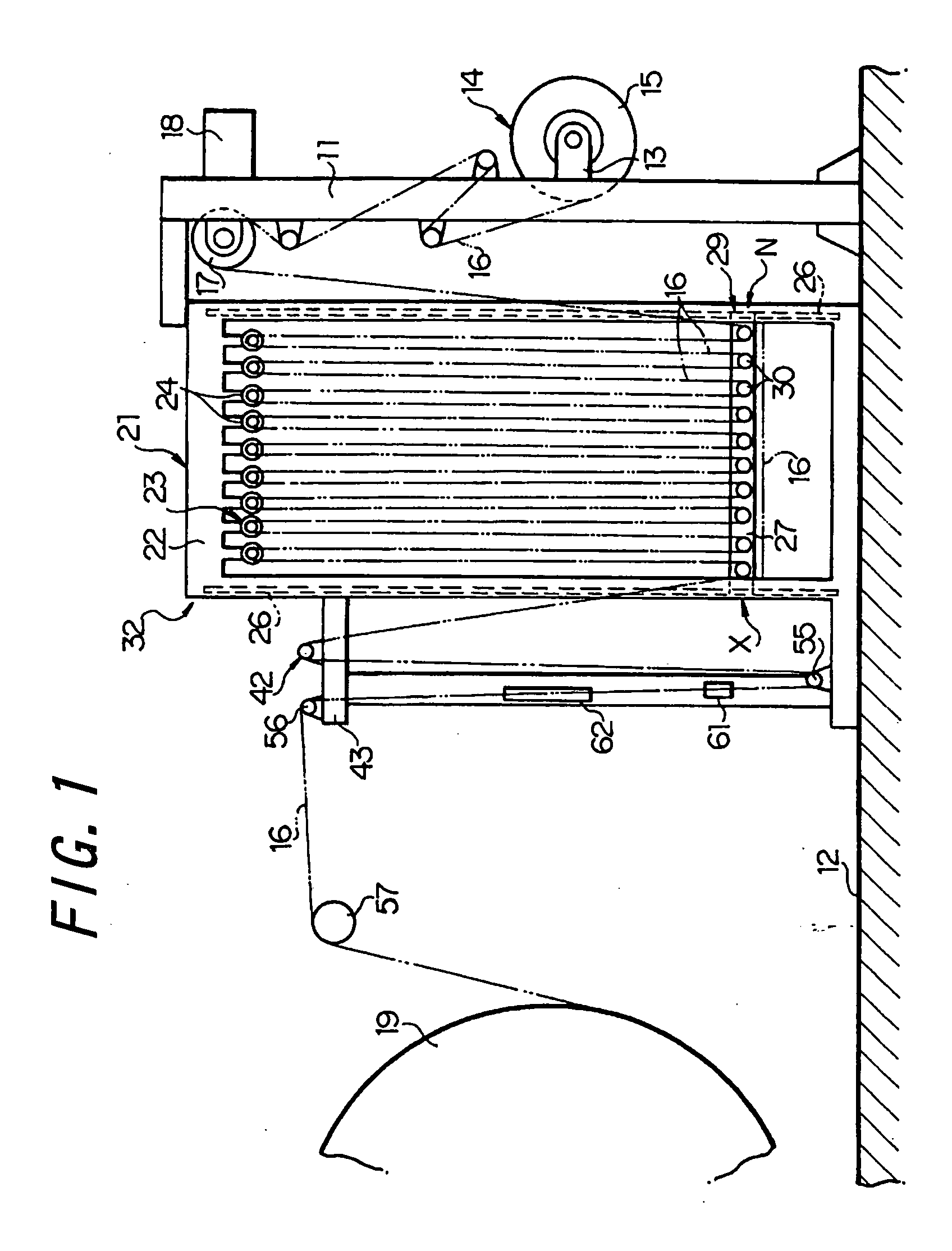
[0008] With this aspect of the present invention, the plurality of temporarily storing means having the upper and lower rollers around which the linear body forming a festoon is alternately and sequentially wound are arranged parallel with each other in a lateral direction and the linear body is led by the guiding means to the inlet from the outlet of the temporarily storing means adjacent to each other so that the same linear body sequentially passes through all the temporarily storing means while forming the festoon, and hence, when the temporarily stored linear body has the same length, the longitudinal length of the temporary storage device can be formed rather shorter than that of a conventional device and, more particularly, the longitudinal length of the temporary storage device can be shortened approximately to a length obtained by dividing the longitudinal length of the conventional device by the number of the temporarily storing means, whereby the temporary storage device can be generally formed compact and easily installed also in an existing equipment.
[0012] According to such features of the present invention, when guiding the linear body from the outlet to the inlet of the temporarily storing means adjacent to each other, it is possible to effectively suppress deviation, collapse, bend and others of the linear body.
[0016] According to such features of the present invention, the abnormal tensile force detecting means can be inexpensively manufactured with a simple configuration.

Problems solved by technology

However, in such conventional temporary storage method / apparatus for a linear body, since the length of the linear body which is temporarily stored is very large, the length of the temporary storage device in the longitudinal direction (substantially equal to the distance between the upper roller at the upstream end and the upper roller at the downstream end) also becomes considerably large.
Hence, there may arise a problem that assurance of the installation space in the existing equipment becomes difficult, due to the increased size of the entire device.

Method used


Image

  • Method and device for temporarily storing linear body
  • Method and device for temporarily storing linear body
  • Method and device for temporarily storing linear body

Examples


Embodiment Construction

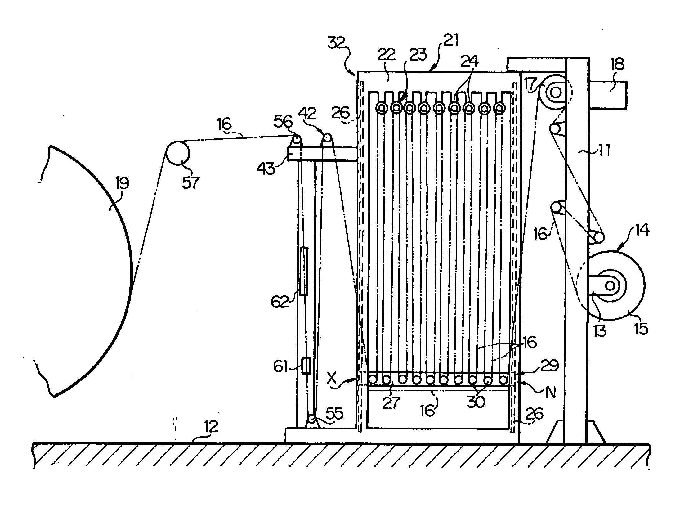
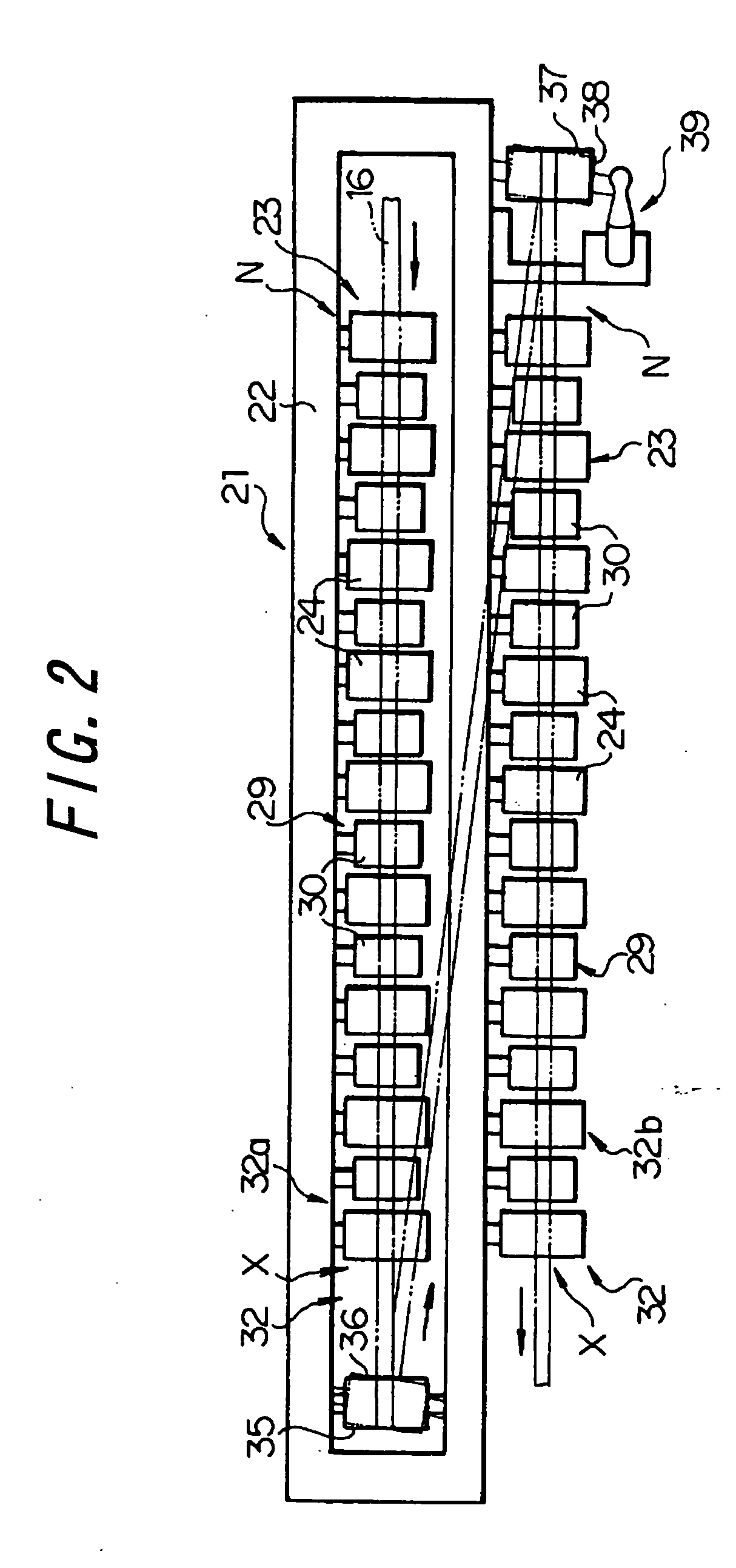
[0021] An embodiment according to the present invention will now be described hereinafter with reference to the accompanying drawings. In FIGS. 1, 2 and 3, reference numeral 11 denotes a support frame which is set on a floor face 12 and extends in a substantially vertical direction, a winding roll 14 is rotatably supported at a central portion of this support frame 11 in the vertical direction through a bearing 13, and this winding roll 14 comprises a cylindrical reel 15 and a linear body 16 wound around the reel 15 multiple times. Reference numeral 17 designates a wind-off roller which is supported at an upper end portion of the support frame 11, and the linear body 16 drawn from the winding roll 14 is wound around this wind-off roller 17. Further, upon receiving a driving force from a motor 18 fixed to the support frame 11, this wind-off roller 17 rotates and takes the linear body 16, and then sequentially winds off the linear body 16 while allowing traveling from the winding roll...


PUM


Abstract

A temporary storage device (21) includes a plurality of temporarily storing means (32), two in the disclosed embodiment, arranged parallel with each other in a lateral direction, wherein a linear body (16) is led from the outlet (X) of the temporarily storing means (32a) to the inlet (N) of the temporarily storing means (32b) by a guide means (39) so that, when the length of the temporarily stored linear body (16) is the same as a conventional one, the longitudinal length of the temporarily storing device (21) can be formed rather shorter than that of a conventional device and more specifically, the longitudinal length of the temporarily storing device (21) can be shortened approximately to a length obtained by dividing the longitudinal length of the conventional device by the number (i.e., two in this case) of the temporarily storage means (32). The temporarily storing device (21) can be thus generally made compact and easily installed also in an existing equipment.

Description

TECHNICAL FIELD [0001] The present invention relates to a temporary storage method and device for temporarily storing an elongate linear body while forming a festoon. BACKGROUND ART [0002] As a temporary storage device for a linear body, the present applicant has recently proposed one as disclosed in JP-A-2002-316769. This device includes a plurality of freely rotatable upper rollers which are arranged on a straight line, having their rotary axes parallel to each other, and a plurality of freely rotatable lower rollers which are respectively arranged immediately below the spaces between the adjacent upper rollers and adapted to be relatively moved toward and away from the upper rollers, having their rotary axes parallel to those of the upper rollers, wherein the device forms a festoon by alternately and sequentially winding about the upper and lower rollers a linear body traveling in the longitudinal direction. [0003] Further, in this known device, the upper and lower rollers are sp...

Claims


Application Information

Patent Timeline
IPC IPC(8): B65H23/16B65H51/22B65H20/34B65H51/20B65H57/14B65H57/26B65H59/36B65H63/032
CPCB65H20/34B65H57/14B65H57/26B65H59/36B65H63/0321B65H2801/93
Inventor NAWATA, SATORU
Owner BRIDGESTONE CORP
Learn More