Reaction chamber

a technology of reaction chamber and volume, which is applied in the field of reaction chamber or reaction volume, can solve the problems of affecting the size of blower or compressor used, affecting the balance of energy, and the range of the electric motor is relatively short, so as to reduce the flow resistance through the reaction volume, and minimize the flow resistance and dynamic pressure of the flowing gas

Inactive Publication Date: 2006-06-01
VALENCE CORP
View PDF10 Cites 1 Cited by
  • Summary
  • Abstract
  • Description
  • Claims
  • Application Information

AI Technical Summary

Benefits of technology

[0007] Other factors that enter into the reaction volume design are the need for radiation shielding from X-rays produced both by the electron source itself and in the reaction volume structure, and to minimize the pressure drop and dynamic pressure of the gas flowing through the chamber. Dimensions of air flow paths within the reaction volume need to be designed to accommodate the flow to minimize flow resistance and dynamic pressur

Problems solved by technology

Electrons have a relatively short range in gases, depositing a large amount of their energy more or less uniformly within a short distance, then losing the balance of ene

Method used


Image

  • Reaction chamber
  • Reaction chamber
  • Reaction chamber

Examples


Embodiment Construction

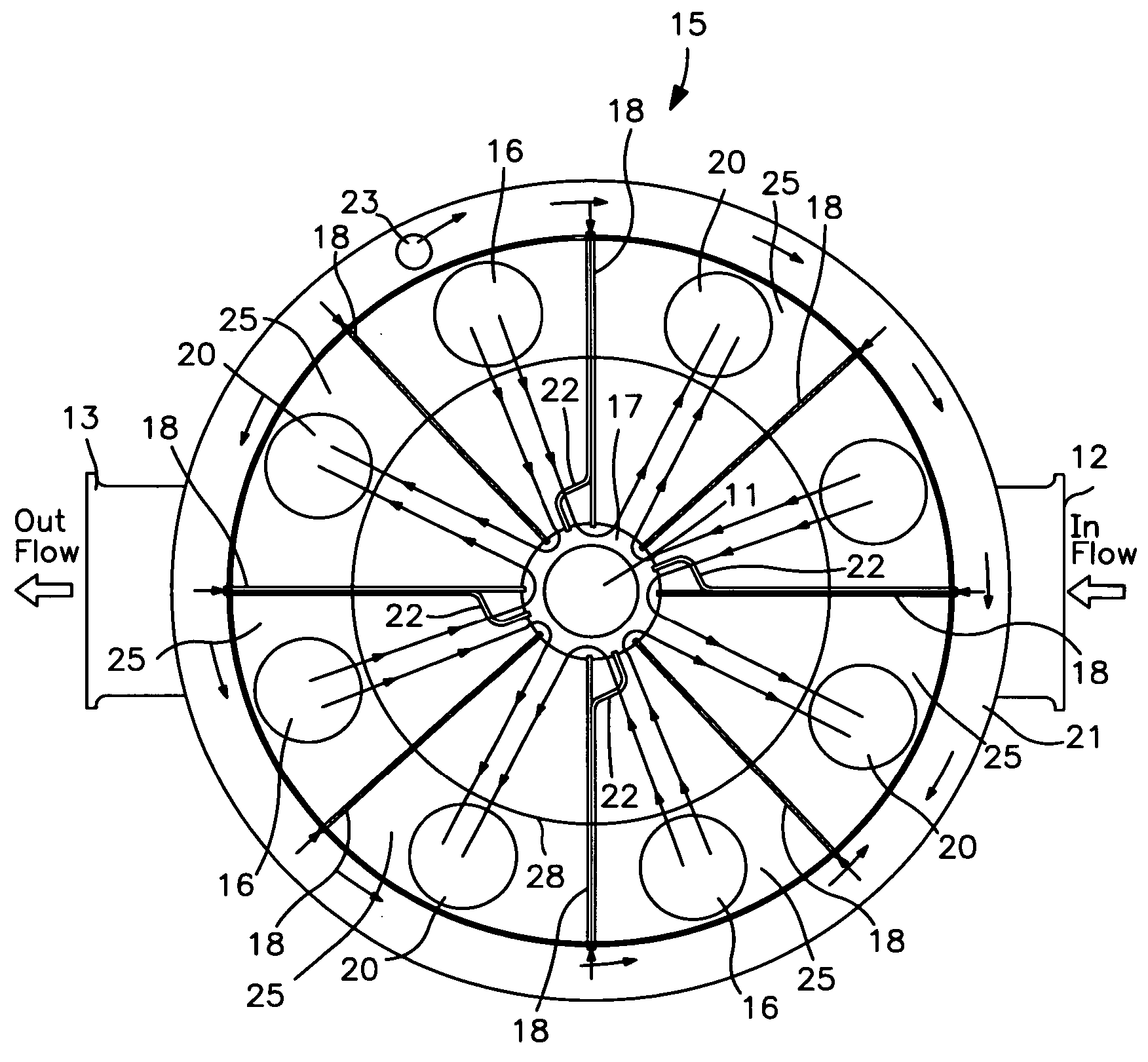
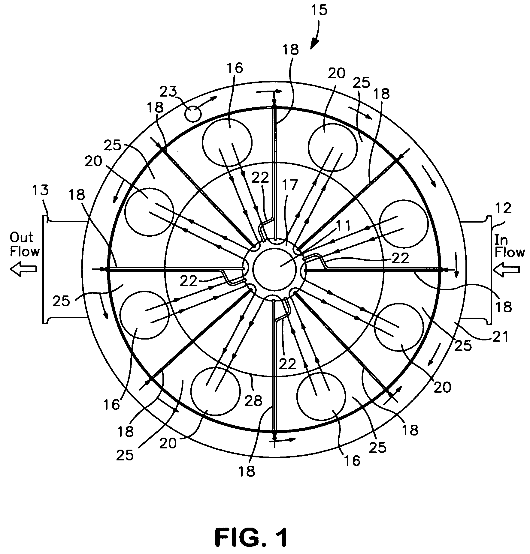
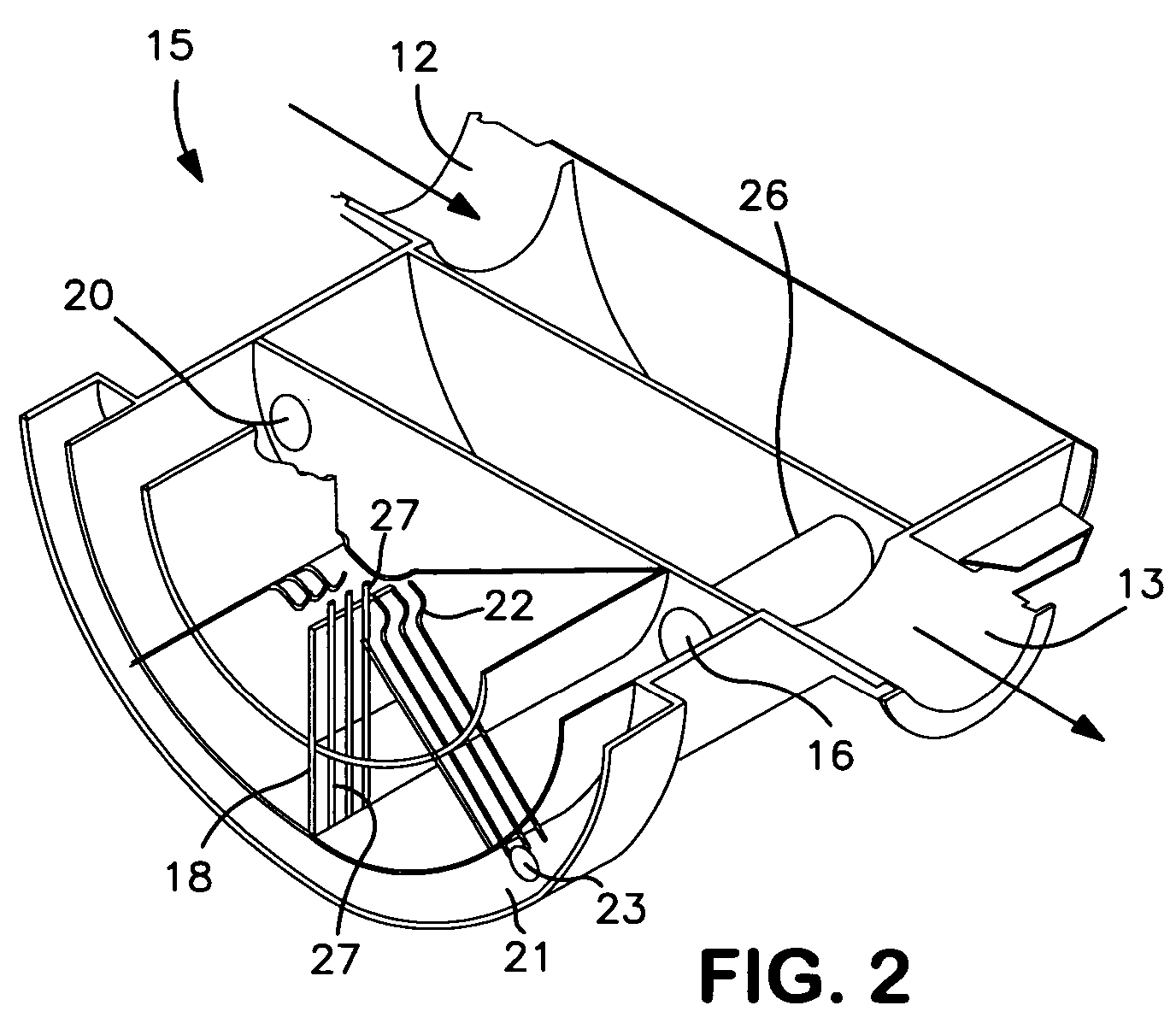
[0011] The geometry of the electron source is a major factor in how the chamber should be designed in order to accomplish the objectives of efficient treatment of a flowing gas. In this instance, a cylindrical source is used since it appears to offer the greatest possibility of a highly efficient treatment system as will be further described herein. The reaction chamber is optimized for an extended cylindrical source as shown in FIG. 1 or for a cylindrical source like that discussed in FIG. 1. The source may be segmented around its periphery, either into a single segment of any angular extension, on into symmetrically or asymmetrically arranged segments of any chosen angular segment or segments. Such a source is fully described in pending application Ser. No. 10 / 822,890 incorporated herein by reference above. The preferred source for this invention is one that provides an output around its entire periphery.

[0012] For a cylindrical source of electrons, the preferred approach is to c...


PUM


Abstract

A novel reaction chamber is described for the treatment of gases which either have a noxious odor or include toxic elements. The chamber is for treatment of the gases with energetic electrons and uses an extended electron source in the center of a chamber volume which creates electrons that move out of the source and radially into the chamber. The gases are flowed into the area of the source and away from the source as to result in uniform and efficient exposure of the flowing gases.

Description

FIELD OF THE INVENTION [0001] This invention has to do with reaction chambers or reaction volumes for efficient energy transfer to gases. In particular, the objective is to optimize the exposure of contaminated gases to energetic electrons generated by a symmetrical electron beam source shaped as an extended cylinder. BACKGROUND OF THE INVENTION [0002] Energetic electrons are used today to neutralize toxic gases and to reduce noxious odors. Although some interest has been expressed in the shape of the chamber in which such treatments occur, in fact to date, the emphasis has not been one of great interest in optimizing chambers for efficient treatment. Various patents exist in this field and some do discuss the reaction chambers. For example in U.S. Pat. No. 5,319,211, a detoxification plenum or tank is illustrated in which electrons attack gases moving through. Also referred to in that patent are U.S. Pat. Nos. 4,507,265; 5,015,443; 4,569,642; and 4,915,916, patents all dealing with...

Claims


Application Information

Patent Timeline
IPC IPC(8): A61N5/00
CPCB01D53/007B01D2259/812B01J19/085B01J19/24B01J2219/00247B01J2219/00765B01J2219/1943B01J2219/1945
Inventor DALLY, EDGAR B.PAUL, JAMES C.
Owner VALENCE CORP
Why Eureka
Try Eureka