Gas detection system

a detection system and gas sensor technology, applied in the field of systems, can solve the problems of increasing power consumption, accelerating the deterioration of the gas sensor, and extremely high power consumption of the heater for heating the gas sensor, so as to achieve the effect of suppressing power consumption

Active Publication Date: 2006-06-01
HITACHI LTD
View PDF7 Cites 33 Cited by
  • Summary
  • Abstract
  • Description
  • Claims
  • Application Information

AI Technical Summary

Benefits of technology

[0022] According to the system control as described above, power supply to the heater can be restricted only to the required minimum period for the measurement at high accuracy and the power consumption can be suppressed.

Problems solved by technology

Referring to the power consumption of the gas sensors per se, in a case where it is necessary to use the gas sensor under heating in order to maintain the high measuring accuracy of the gas sensor, the power consumption in a heater for heating the gas sensor is extremely high.
Heating of the gas sensor increases the power consumption and also accelerate deterioration of the gas sensor.
Particularly in a case, for example, of using a dry cell as a power supply for the sensor node, if the power consumption of the heater that heats the gas sensor is large, it can not cope with the detection for gas leakage over a long period of time.

Method used


Image

  • Gas detection system
  • Gas detection system
  • Gas detection system

Examples


Embodiment Construction

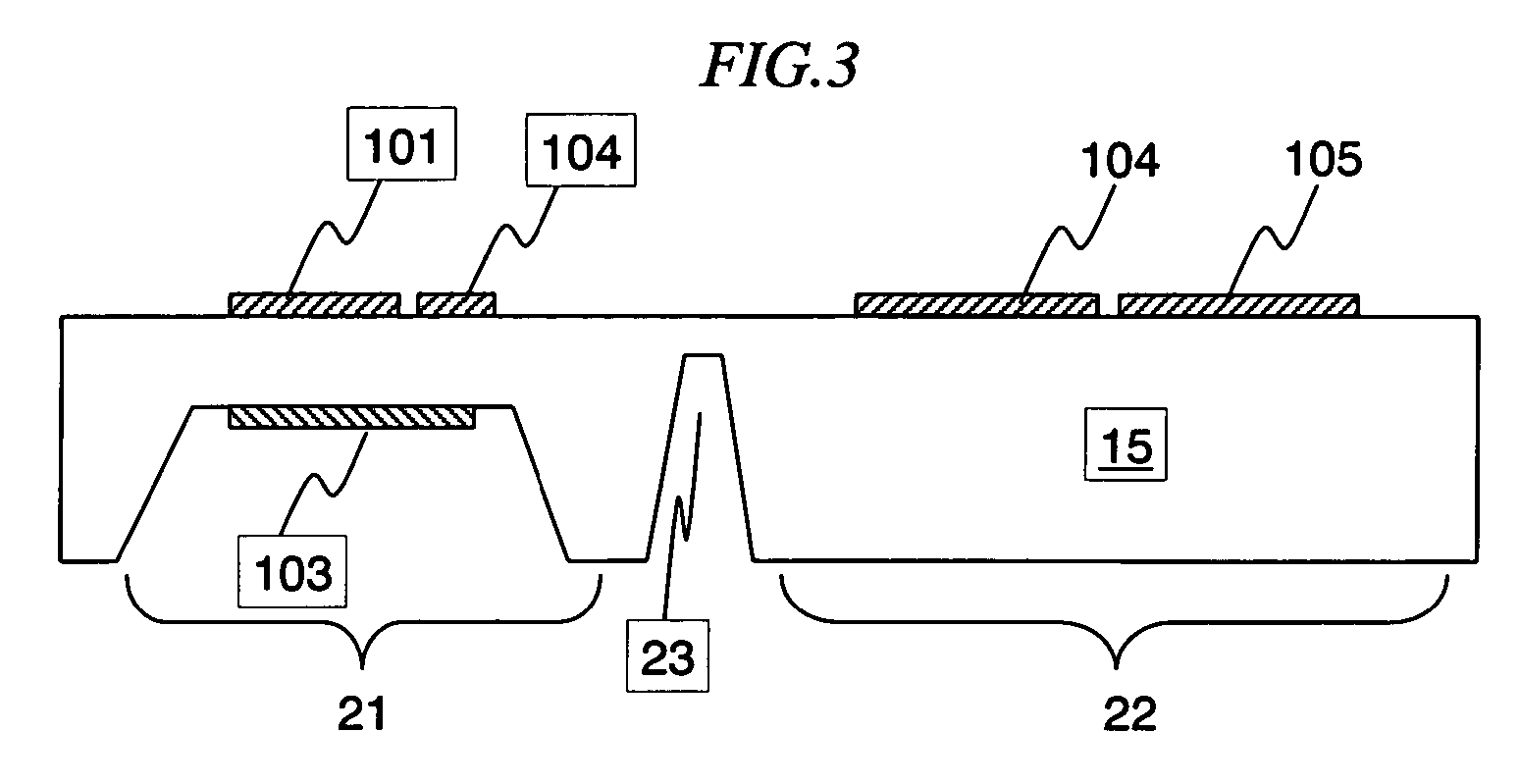
[0034] An example of the constituent factors of the present invention is to be shown at first with reference to FIG. 1 to FIG. 3.

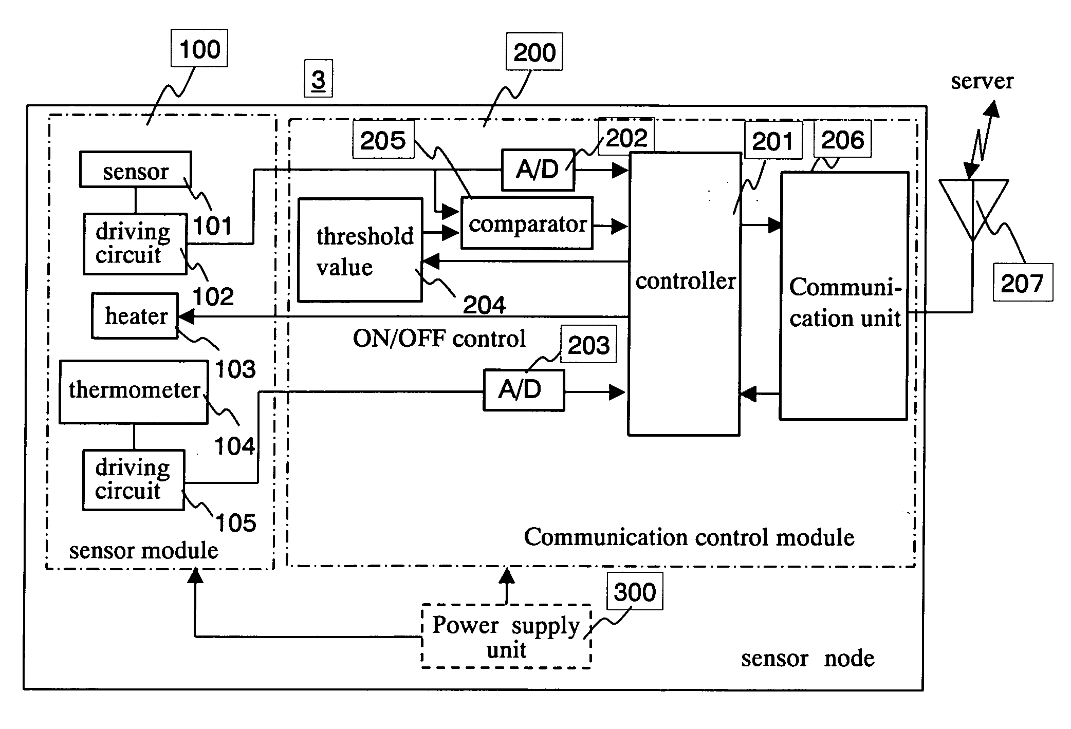
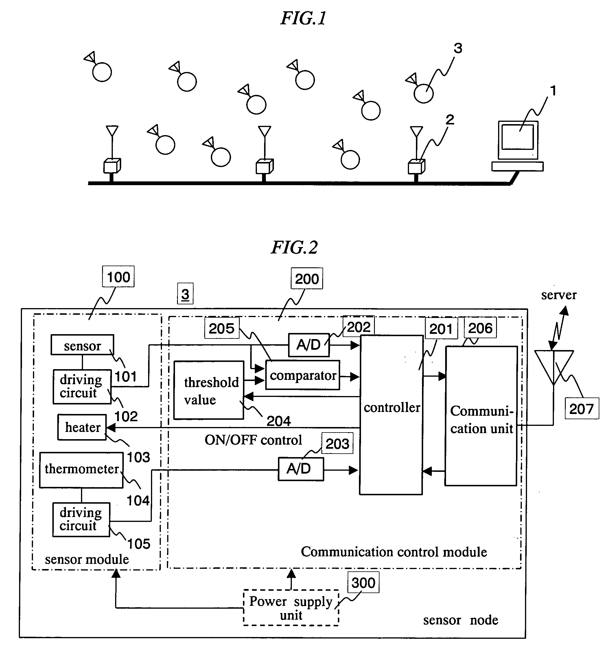
[0035]FIG. 1 is a conceptional view for the system constitution of the present invention. Sensor nodes each having a gas sensing function and a wireless communication function are provided in plurality. On the other hand, access points 2 connected with a server 1 are located at plural positions and the respective sensor nodes 3 are in communication by way of wireless communication to the server 1 through the access points 2. In the following example, explanation is to be made assuming that each of the sensor nodes 3 is in communication by way of the wireless communication with the server 1 in accordance with the configuration shown in FIG. 1 but the effect of power saving can also be obtained by the same flow in a case of wired communication. Further, for the simplicity of the explanation, description is to be made to an example of leakage of deleterious ...


PUM

PropertyMeasurementUnit
temperatureaaaaaaaaaa
thresholdaaaaaaaaaa
threshold valueaaaaaaaaaa

Abstract

A gas detection system capable of suppressing the power consumption of the system using gas sensors required for heating for measurement at high accuracy, comprising a server and a plurality of gas sensors connected by way of wireless communication with the server, in which each of the gas sensors is provided with a heater, a controller for controlling the ON-OFF for the power supply to the heater and a comparator for comparing the detected gas concentration with a predetermined threshold value. In the gas detection system, electric power is not usually supplied to the heater in each of the gas sensors and the gas sensor measures the gas concentration at a low accuracy and always compares it with the threshold value. In a case where the gas concentration exceeds the threshold value in one of the gas sensors, it turns the heater of its own to ON thereby switching the measurement to that at high accuracy and turns the heater to OFF upon completing the measurement. At the same time, it informs the detection for the excess of threshold value to the server and the server lowers the threshold value of the gas sensors in the vicinity of the gas sensor that has informed the detection for the excess of threshold value to make the monitoring level severer.

Description

CLAIM OF PRIORITY [0001] The present application claims priority from Japanese application JP-2004-341897 filed on Nov. 26, 2004, the content of which is hereby incorporated by reference into this application. FIELD OF THE INVENTION [0002] The present invention relates to a system for detecting the change of the gas concentration and, more in particular, it relates to a system control technique suitable to a detection system of monitoring the distribution of gas concentration by arranging a plurality of gas sensors. BACKGROUND OF THE INVENTION [0003] Gas sensors include various types. For flammable gas sensors, for example, contact combustion type, semiconductor type, heat conduction type, infrared absorption, etc. have been known as described in JIS M 7626 “Stational Type Combustible Gas Detection Alarm”. Further, as a system of using thin films or thick films, an FET system (system of depositing gas sensing membrane on a gate electrode of FET and reading the change of the gate pot...

Claims


Application Information

Patent Timeline
Patent Type & Authority Applications(United States)
IPC IPC(8): G01N7/00
CPCG01N33/0016G01N33/0022G01N33/0031G01N27/123G01N33/0063
Inventor YOKOSAWA, KOICHINAKANO, SADAKIGOTO, YASUSHI
Owner HITACHI LTD
Why Eureka
Try Eureka