Switching matrix apparatus for semiconductor characteristic measurement apparatus

a technology of semiconductor characteristics and matrix apparatus, which is applied in the direction of measurement devices, instruments, computing, etc., can solve the problems of increasing the density of led arrangement inside the led display unit, the difficulty of a user to quickly and precisely determine the position currently specified with the light pen, and the need to increase the density of led arrangement, so as to achieve the effect of reducing the time of light emission, and reducing the cost of operation

Inactive Publication Date: 2006-06-01
AGILENT TECH INC
View PDF0 Cites 35 Cited by
  • Summary
  • Abstract
  • Description
  • Claims
  • Application Information

AI Technical Summary

Benefits of technology

[0024] Furthermore, in the present invention, it is preferable that the period of the light emission is shortened when the light-receiving portion detects light from the indicator light-emitting portion.
[0025] According to the present invention, the user can quickly and precisely determine the position of a light-emitting portion that is about to be selected or has been selected and the position of an intended light-emitting portion, on a matrix LED display unit of the switching matrix apparatus. This configuration allows the user to quickly and precisely perform the switching in the switching matrix apparatus used for connecting a plurality of input terminals and a plurality of output terminals.
[0026] Furthermore, according to the present invention, the switching matrix apparatus can display the position of a light-emitting portion that is about to be selected or has been selected with the light pen, using LEDs in which the emitted light color, brightness, and flashing pattern are adjusted. This configuration allows the user to simultaneously confirm the position that is about to be selected or has been selected by the user and the status of each relay switch.
[0027] Furthermore, in the present invention, the switching matrix apparatus uses an existing LED display unit, and thus no additional cost is incurred.

Problems solved by technology

However, in the conventional apparatus described above, the number of LEDs arranged in a matrix is large, and thus it is difficult for a user to quickly and precisely determine the position currently specified with the light pen and the intended position, based on the display numbers displayed on the edge of the LED display unit.
This will become an even more serious problem if the number of switching matrixes increases in future; and thus the density in the LED arrangement inside the LED display unit needs to be increased.

Method used


Image

  • Switching matrix apparatus for semiconductor characteristic measurement apparatus
  • Switching matrix apparatus for semiconductor characteristic measurement apparatus
  • Switching matrix apparatus for semiconductor characteristic measurement apparatus

Examples


Embodiment Construction

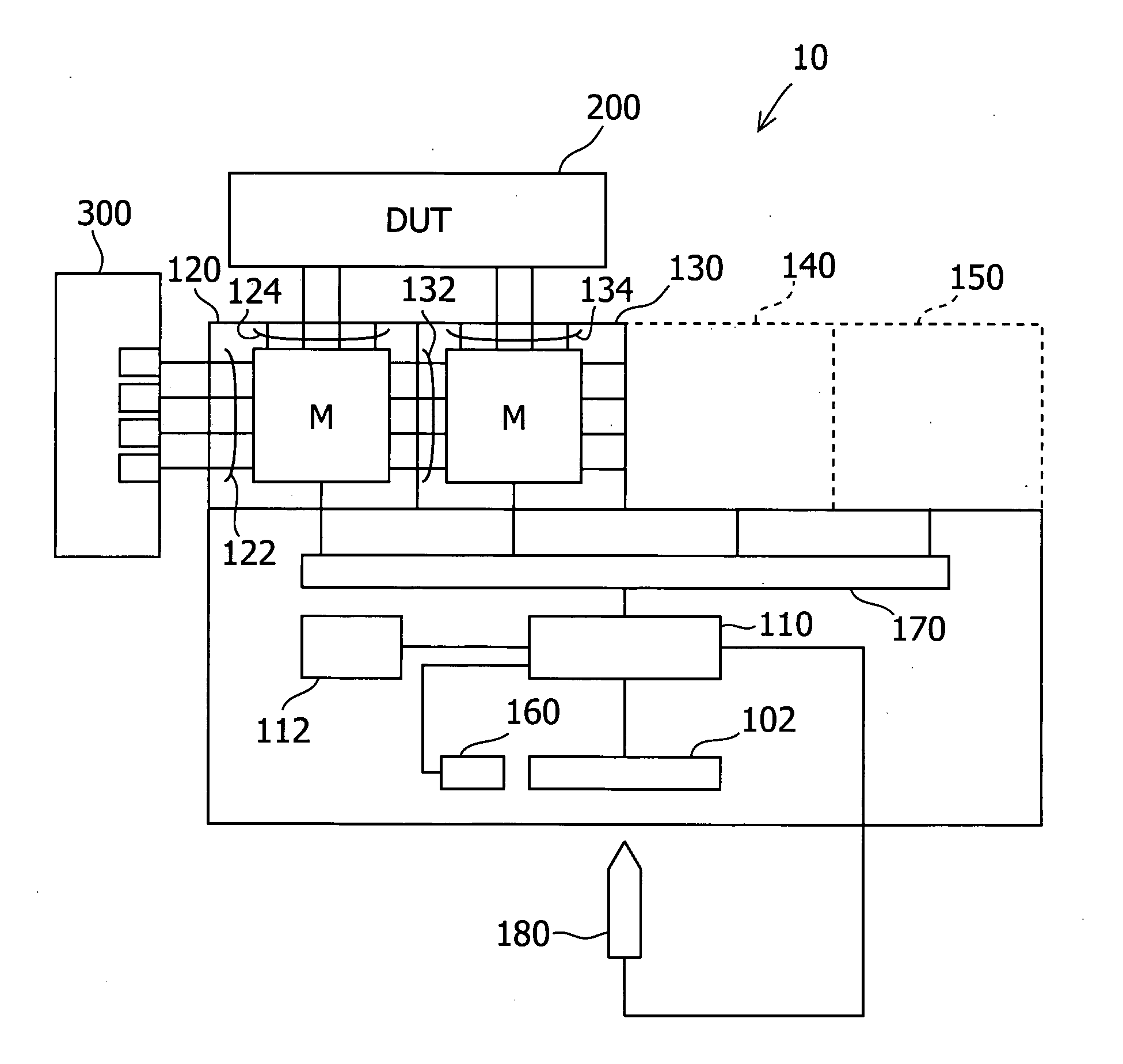
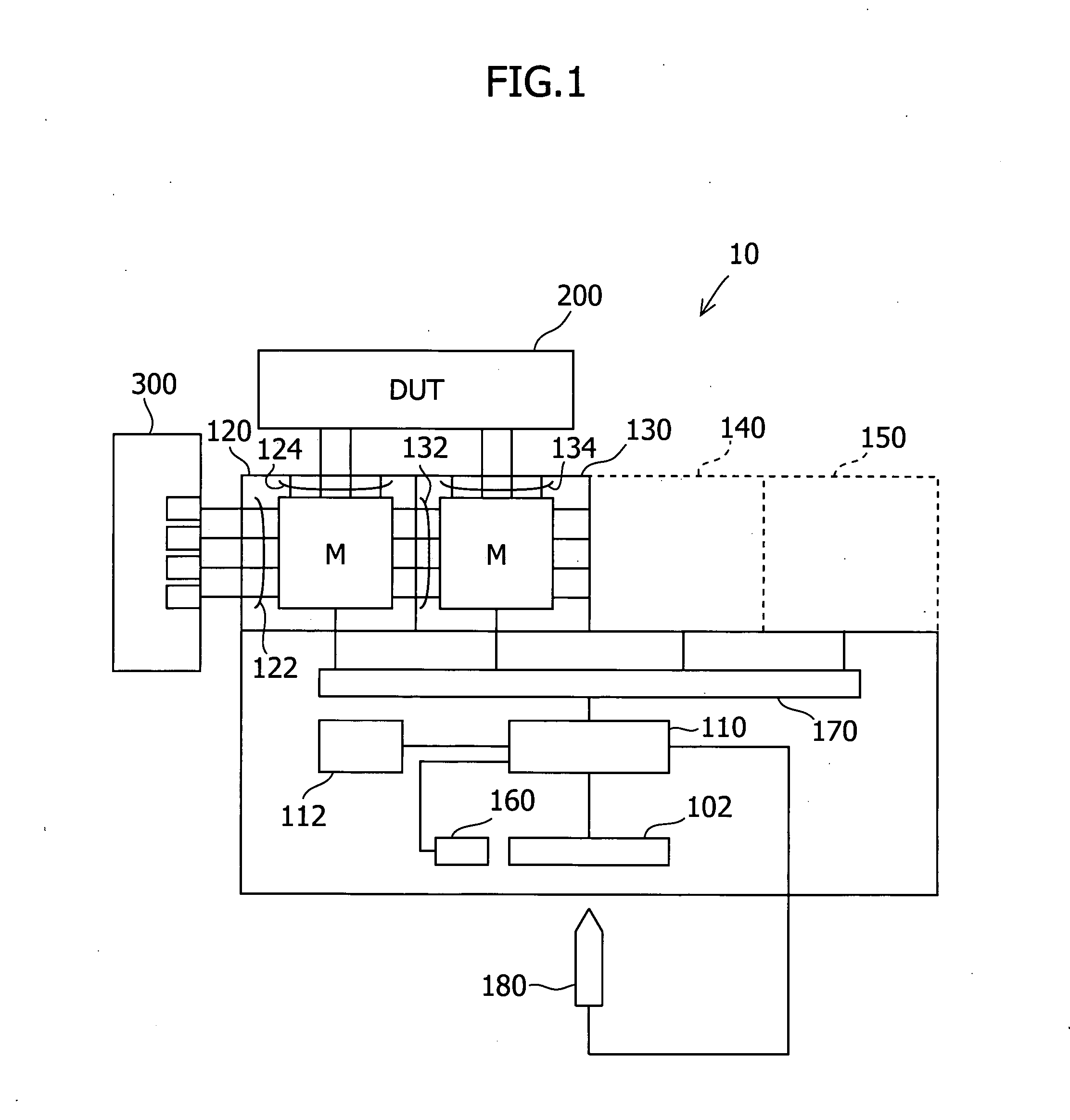
[0037] Embodiments of the present invention are described below with reference to the accompanying drawings. FIG. 1 is a block diagram showing the configuration of a switching matrix apparatus 10 according to an embodiment of the present invention. The switching matrix apparatus 10 of this embodiment controls connections between a semiconductor-characteristic measurement apparatus 300, such as an LCR meter, and a device under test (DUT) 200, which is probed by a probe apparatus (not shown) or the like.

[0038] The switching matrix apparatus 10 of the embodiment of the present invention includes a first card 120 and a second card 130, which have a plurality of row terminals 122 and 132 and column terminals 124 and 134, respectively. In this case, for simplicity, the row terminals 122 are connected to the semiconductor-characteristic measurement apparatus 300 and the column terminals 124 and 134 are connected to the DUT 200. That is, in the switching matrix apparatus 10, the row termin...


PUM


Abstract

The switching matrix apparatus is provided with a plurality of relay switches for opening and closing the electrical connections between a plurality of input terminals and a plurality of output terminals, and a display unit in which a plurality of light-emitting portions are arranged in a matrix in correspondence with the respective relay switches and in which indicators indicating the positions of the light-emitting portions in at least multiple columns and rows are displayed along at least two sides of the light-emitting portions arranged in a matrix. In order to facilitate confirmation of the position of a light-emitting portion that is about to be selected or has been selected with a light pen on the display unit, light is emitted by at least one other light-emitting portion relating to the light-emitting portion that is about to be selected or has been selected.

Description

FIELD OF THE INVENTION [0001] The present invention relates to a switching matrix apparatus for the measurement of semiconductor characteristics. In particular, the present invention relates to an apparatus that clearly indicates the position pointed at with a light pen on a matrix LED display unit. BACKGROUND OF THE INVENTION [0002] Conventionally, a switching matrix apparatus is used to easily change the connections between multiple semiconductor-characteristic measurement apparatuses and a device under test (hereinafter referred to as “DUT”). The switching matrix apparatus connects input ports and output channels in arbitrary combinations in accordance with an instruction from a user. In this case, depending on the kind of measurements, one or more semiconductor-characteristic measurement apparatuses, including an LCR (inductance-capacitance-resistance) meter, are connected to the input ports, and a probe apparatus or the like to be connected to the target DUT is connected to the...

Claims


Application Information

Patent Timeline
Patent Type & Authority Applications(United States)
IPC IPC(8): G09G5/00
CPCG01R31/2844G01R31/31926G06F3/0386G09G3/006G09G3/32
Inventor IWASAKI, KATSUHITO
Owner AGILENT TECH INC
Why Eureka
Try Eureka