
Switching type power source device and magnetio resonance imaging device using the same

a technology of switching type and power source device, which is applied in emergency protective arrangements for limiting excess voltage/current, dc-ac conversion without reversal, instruments, etc., can solve the problems of preventing the acquisition of high-quality mri images, reducing the accuracy of current supplied to the generation of magnetic field using coils working as load, etc., to achieve the effect of reducing current ripple and high voltag

Inactive Publication Date: 2006-06-01
HITACHI MEDICAL CORP
View PDF2 Cites 30 Cited by
  • Summary
  • Abstract
  • Description
  • Claims
  • Application Information

AI Technical Summary

Benefits of technology

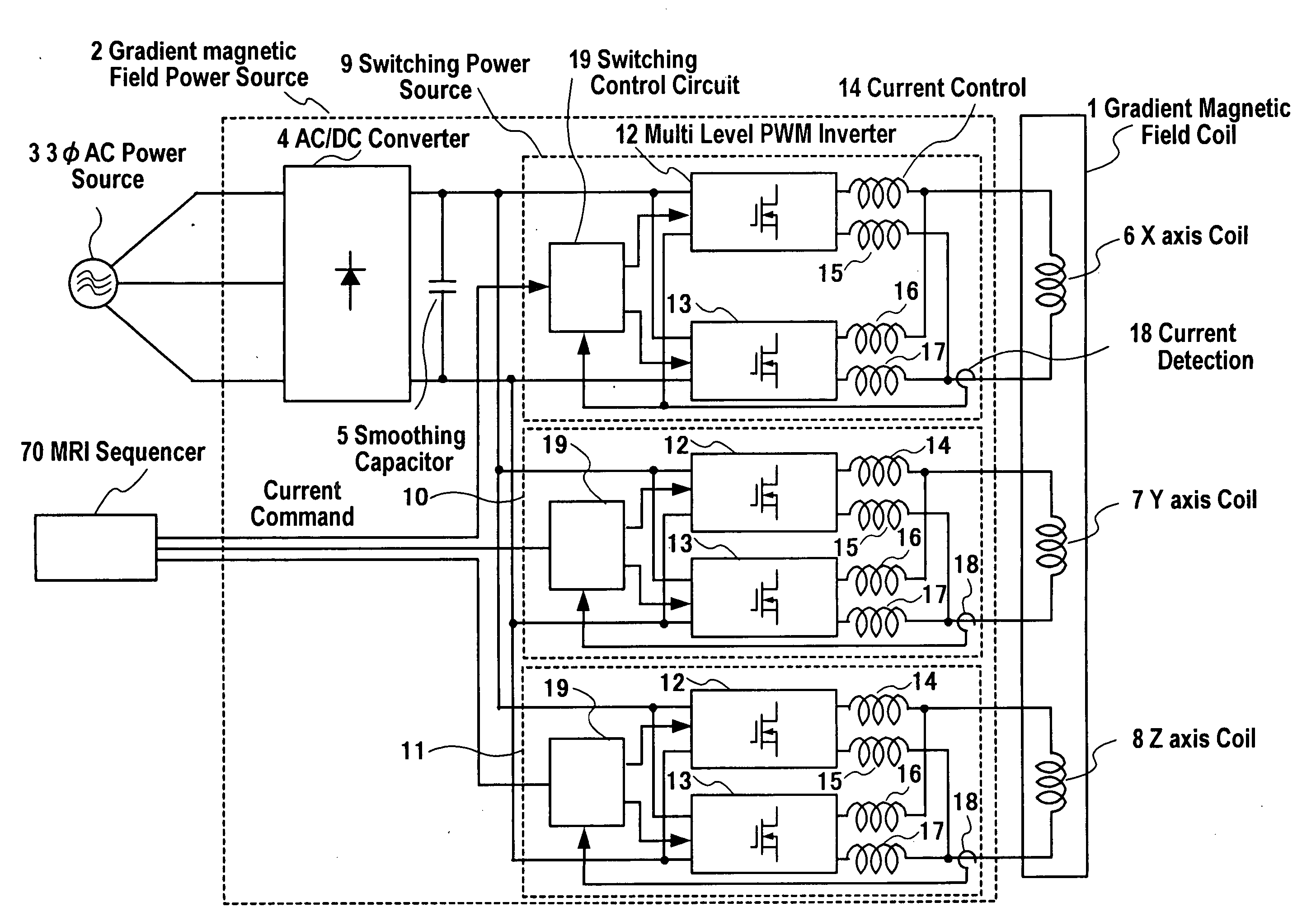
[0005] For achieving the above object, the present invention provides a switching type power source device for magnetic field generation coils used for an MRI device in which a switching power source is constituted by a first and a second multi level PWM inverter having a same number of potential levels and being connected in parallel relation each other with respect to each of the magnetic field generation coils for the MRI device working as a load as well as a switching control circuit for drive controlling the first and the second multi level PWM inverter is constituted to drive control switching phases of the first and the second multi level PWM inverter in a manner to shift each other, thereby, ripples of currents output from the first and the second multi level PWM inverter are canceled out each other and a current with further reduced ripple components as a whole can be supplied to the load.

Problems solved by technology

Although now a day power source devices for MRI devices are required of rising the voltage and increasing the current for high speed imaging, however, even when the above referred to multi level PWM inverters are used for a switching power source, a current ripple is still caused during the switching operation, the accuracy of the current being supplied to magnetic field generation use coils working as a load is decreased, which prevents from acquiring high quality MRI images.

Method used


Image

  • Switching type power source device and magnetio resonance imaging device using the same
  • Switching type power source device and magnetio resonance imaging device using the same
  • Switching type power source device and magnetio resonance imaging device using the same

Examples


Embodiment Construction

[0011] An embodiment of the present invention will be explained with reference to the drawings.

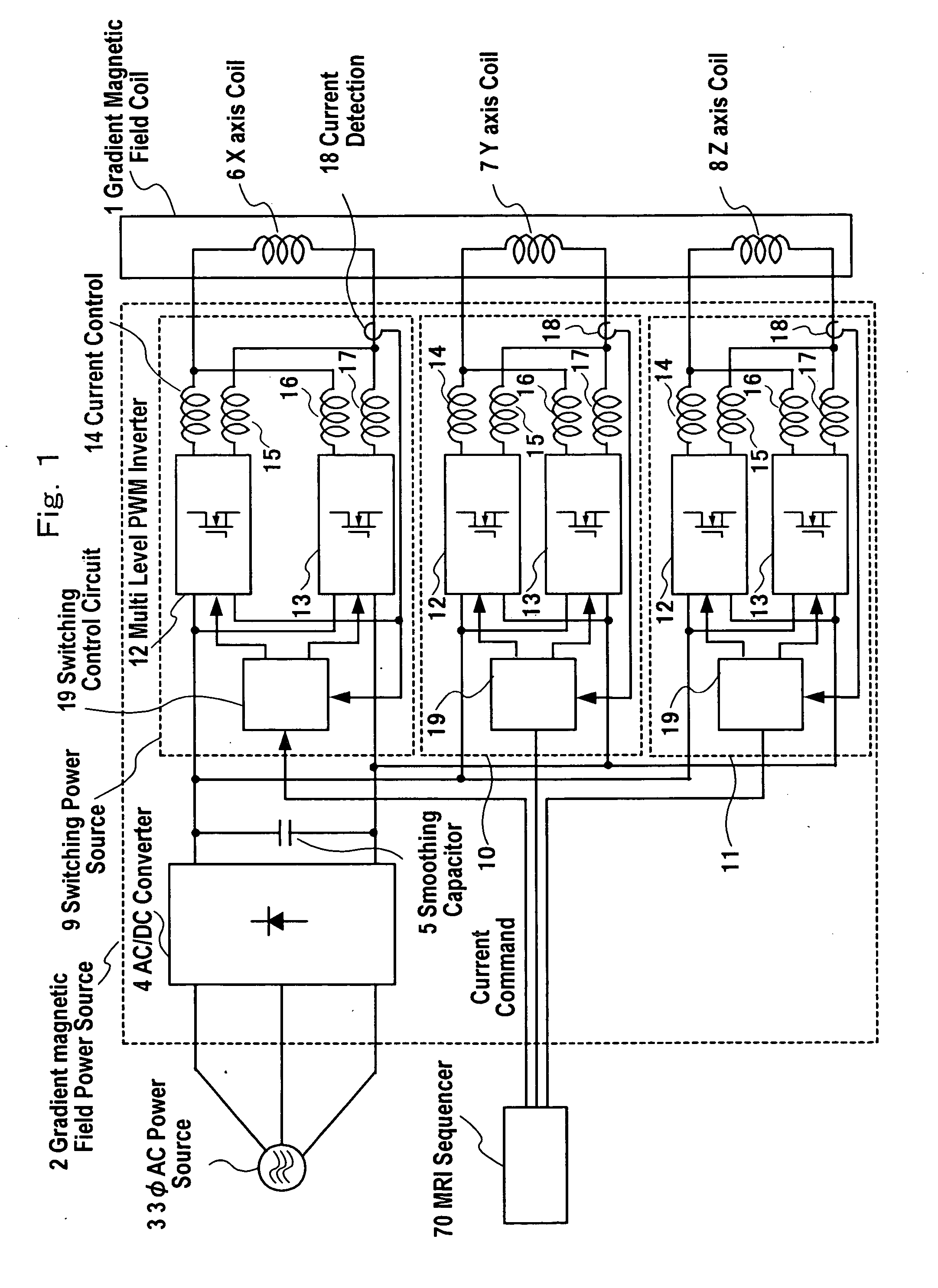
[0012]FIG. 1 shows a block constitutional diagram when a switching type power source device according to one embodiment of the present invention is applied to gradient magnetic field coils for an MRI device.

[0013] A gradient magnetic field coil use power source device 2 for the MRI device is constituted in a manner being supplied of an electric power from a three phase AC power source 3 and connected to a gradient magnetic field use coil 1 working as a load to supply a current thereto. The gradient magnetic field coil use power source device 2 for the MRI device is provided with an AC / DC converter 4 which is connected to the three phase AC power source 3 and converts a three phase AC voltage to a DC voltage, a smoothing capacitor 5 which is connected to the output side of the AC / DC converter 4 and smoothes the DC voltage and switching power sources 9˜11 functioning as current amplifiers ...


PUM


Abstract

A switching type power source device used for magnetic field generation coils for an MRI device in which a switching power sources (9˜11) are constituted by a first and a second multi level PWM inverter (12,13) having a same number of potential levels connected in parallel each other with respect to magnetic field generating coils (6˜8) for the MRI device working as a load as well as a switching control circuit (19) for drive controlling the first and the second multi level PWM inverter (12,13) is constituted to drive control the first and the second multi level PWM inverter (12,13) in a manner to shift the switching phases thereof each other, thereby, ripple components in currents output from the first and the second multi level PWM inverter (12,13) are canceled out each other and a current with a further reduced ripple components as a whole can be supplied to the load (6˜8).

Description

FIELD OF THE INVENTION [0001] The present invention relates to a switching type power source device suitable for magnetic field generation use coils namely, static magnetic field, gradient magnetic field or high frequency magnetic field generation use coils for a magnetic resonance imaging device (herein after MRI device) which requires a high current accuracy and comparatively high voltage and large current, for example, 1000˜2000V and 500 A, and an MRI device using the same. CONVENTIONAL ART [0002] Switching type power sources have been largely used as power source devices for MRI devices, and recently, in response to a demand for increasing current thereof, a power source device for magnetic field generation use coils for an MRI device formed by connecting two level PWM inverters in parallel as disclosed, for example, in JP-A-8-211139 has been known. Further, in a field of inverter power sources for driving three phase motors, multi level inverter technology has been drawing atte...

Claims


Application Information

Patent Timeline
IPC IPC(8): H02H7/00G01R33/385H02M7/48H02M7/483H02M7/5387
CPCG01R33/3852H02M7/487H02M7/493H02M2003/1555H02M3/1555H02M1/0043
Inventor DOMOTO, TAKUYATAKANO, HIROSHI
Owner HITACHI MEDICAL CORP
Learn More