Light emitting diode backlight package

a technology of light-emitting diodes and backlights, which is applied in the direction of planar/plate-like light guides, lighting and heating apparatuses, instruments, etc., can solve the problems of poor luminosity along the length of the lgp, incurred energy losses due to the imperfect reflectivity of the native surface, and clearly undesirable situations, etc., to achieve the effect of minimising energy losses

Active Publication Date: 2006-06-01
OPTRONIC SCI LLC
View PDF3 Cites 10 Cited by
  • Summary
  • Abstract
  • Description
  • Claims
  • Application Information

AI Technical Summary

Benefits of technology

[0012] It is another feature of an embodiment of the present invention to provide a light emitting device backlight package, which transmits light along the light guiding plate with minimal energy losses.

Problems solved by technology

However, since conventional LCDs do not have high transmissivities (with most being less than 50% transmissive), it is important that the backlight be as efficient as possible.
For each of these reflections, energy losses are incurred due to the native imperfect reflectivity of the surfaces.
These energy losses, in addition to the inherent inefficiencies they introduce, also lead to poor luminosity along the length of the LGP 11.
This situation is clearly undesirable and methods have been sought to solve these problems.
While the example of FIG. 2 is an improvement over that shown in FIG. 1, the new configuration has, however, created another drawback.
This positioning is awkward and inefficient, causing critical space to be occupied by what is essentially a maintenance device, instead of using that space to contribute to the primary goal of achieving efficient light production.

Method used


Image

  • Light emitting diode backlight package
  • Light emitting diode backlight package
  • Light emitting diode backlight package

Examples


Embodiment Construction

[0020] The present invention will now be described more fully hereinafter with reference to the accompanying drawings, in which exemplary embodiments of the invention are shown. The invention may, however, be embodied in different forms and should not be construed as limited to the embodiments set forth herein. Rather, these embodiments are provided so that this disclosure will be thorough and complete, and will fully convey the scope of the invention to those skilled in the art. In the figures, the dimensions of layers and regions may be exaggerated for clarity of illustration. Like reference numerals refer to like elements throughout.

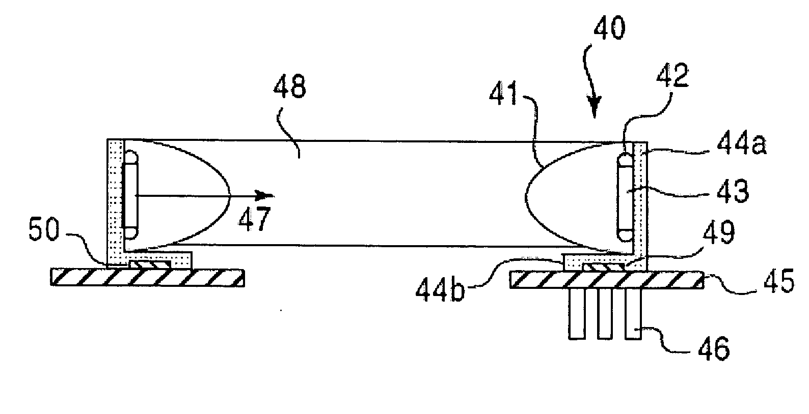
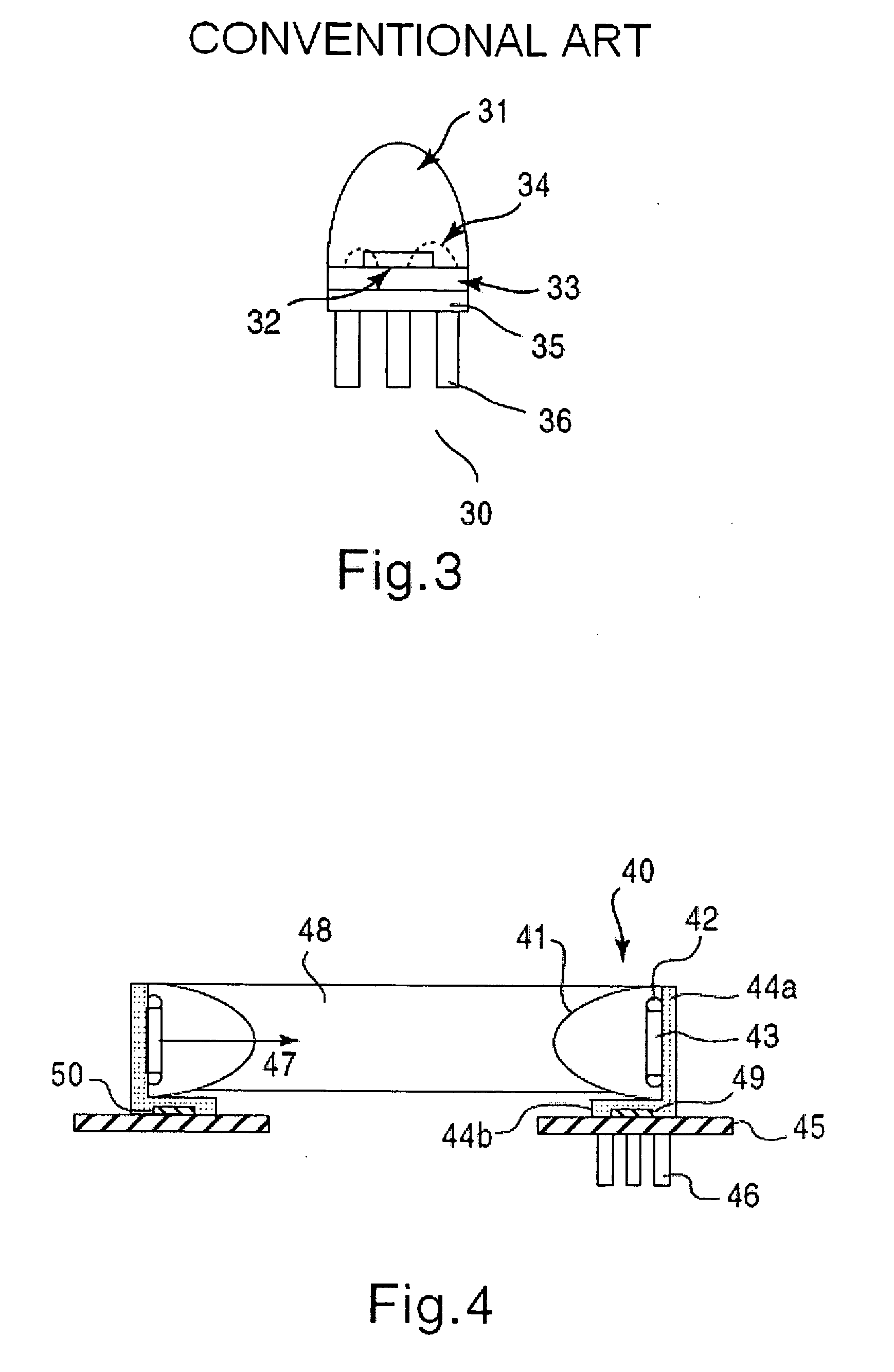
[0021]FIG. 4 illustrates a light emitting device (LED) package incorporating light emitting device (LED) modules 40, according to an embodiment of the present invention. Basic components of LED modules 40 include a LENS 41, conducting wires 42, chip 43, an L shaped fastener formed of a first portion 44A and a second portion 44B, and a PCB 45. In this...


PUM


Abstract

In a light emitting device including a transparent covering, a fastener having a vertical member and a horizontal member, a light-emitting chip disposed on one face of the vertical member and encased by the transparent covering, a circuit board disposed on one face of the horizontal member, at least one conductive means connecting the light-emitting chip to the circuit board, and at least one heat-dissipating plate perpendicularly disposed on the other face of the horizontal member, light may be emitted longitudinally along a light-guiding plate, thus optimizing the travel path of the emitted light, while maintaining a compact shape by enabling placement of the printed circuit board and heat dissipating plates away from a longitudinal axis of the light-guiding plate.

Description

BACKGROUND OF THE INVENTION [0001] 1. Field of the Invention [0002] The present invention generally relates to the packaging of light-emitting device backlights. In particular, the present invention relates to a light-emitting device backlight package which requires minimal space while producing maximum luminosity. [0003] 2. Related Art [0004] Liquid crystal displays (LCDS) are commonly used in televisions, computers, and cellular telephones to display information to their users. The most basic function of the LCD is to act as a light switch, allowing transmission of light in one mode and blocking transmission of light in a second mode. The LCD selectively modulates light from a backlight or a reflector (or a combination of both), with these modes being referred to as transmissive mode and reflective mode, respectively. Backlighting the LCD is a popular method of providing a light source for the LCD, since backlighting the LCD allows good functionality in low ambient light condition...

Claims


Application Information

Patent Timeline
Patent Type & Authority Applications(United States)
IPC IPC(8): F21V7/04H01L33/58H01L33/48
CPCG02B6/0021G02B6/003Y10S362/80H01L2924/3025H01L2924/00H01L2224/48091H01L2924/00014
Inventor CHOU, SHEN-HONGCHOU, HUI-KAI
Owner OPTRONIC SCI LLC
Why Eureka
Try Eureka