Lens holding system, optical pick-up device, and recording/reproducing device

a technology of optical pickup and holding system, which is applied in the manufacture of optical heads, instruments, data recording, etc., can solve the problems of difficult to attach or detach the objective lens, difficult to apply adhesive materials, and difficult to read/write signals from/into optical disks b, so as to achieve the effect of easy attachment and detachment of the objective lens and preventing temperature ris

Inactive Publication Date: 2006-06-01
SHARP KK
View PDF5 Cites 6 Cited by
  • Summary
  • Abstract
  • Description
  • Claims
  • Application Information

AI Technical Summary

Benefits of technology

[0015] The present invention has been attained in view of the problems mentioned above. An object of the present invention is to achieve a lens holding system, and an optical pick up device including the lens holding system, and a recording / reproducing device; the lens holding system (i) being capable of performing attachment and detachment of an objective lens easily and (ii) further being capable of preventing temperature rise, when a lens protector for preventing collision of the objective lens and the optical disk is provided.

Problems solved by technology

In an extreme case, it becomes difficult to read / write a signal from / into the optical disk 300.
However, when a lens protector having the circular shape and entirely surrounding all the periphery of the objective lens as mentioned above is formed so as to protrude toward the optical disk more than the objective lens, there is a problem in that it is difficult to attach or detach the objective lens.
This is because the lens protector hinders the attachment or the detachment.
Moreover, when the objective lens is attached to the lens holder by an adhesive material in the optical pick up device having the lens protector of the shape mentioned above, it is difficult to apply the adhesive material.
Furthermore, when the lens protector entirely surrounds the objective lens, a region from which heat is exhausted is limited.
Accordingly, there arises a problem in that a temperature around the objective lens rises because of heat generated by an objective lens driving coil.

Method used


Image

  • Lens holding system, optical pick-up device, and recording/reproducing device
  • Lens holding system, optical pick-up device, and recording/reproducing device
  • Lens holding system, optical pick-up device, and recording/reproducing device

Examples


Embodiment Construction

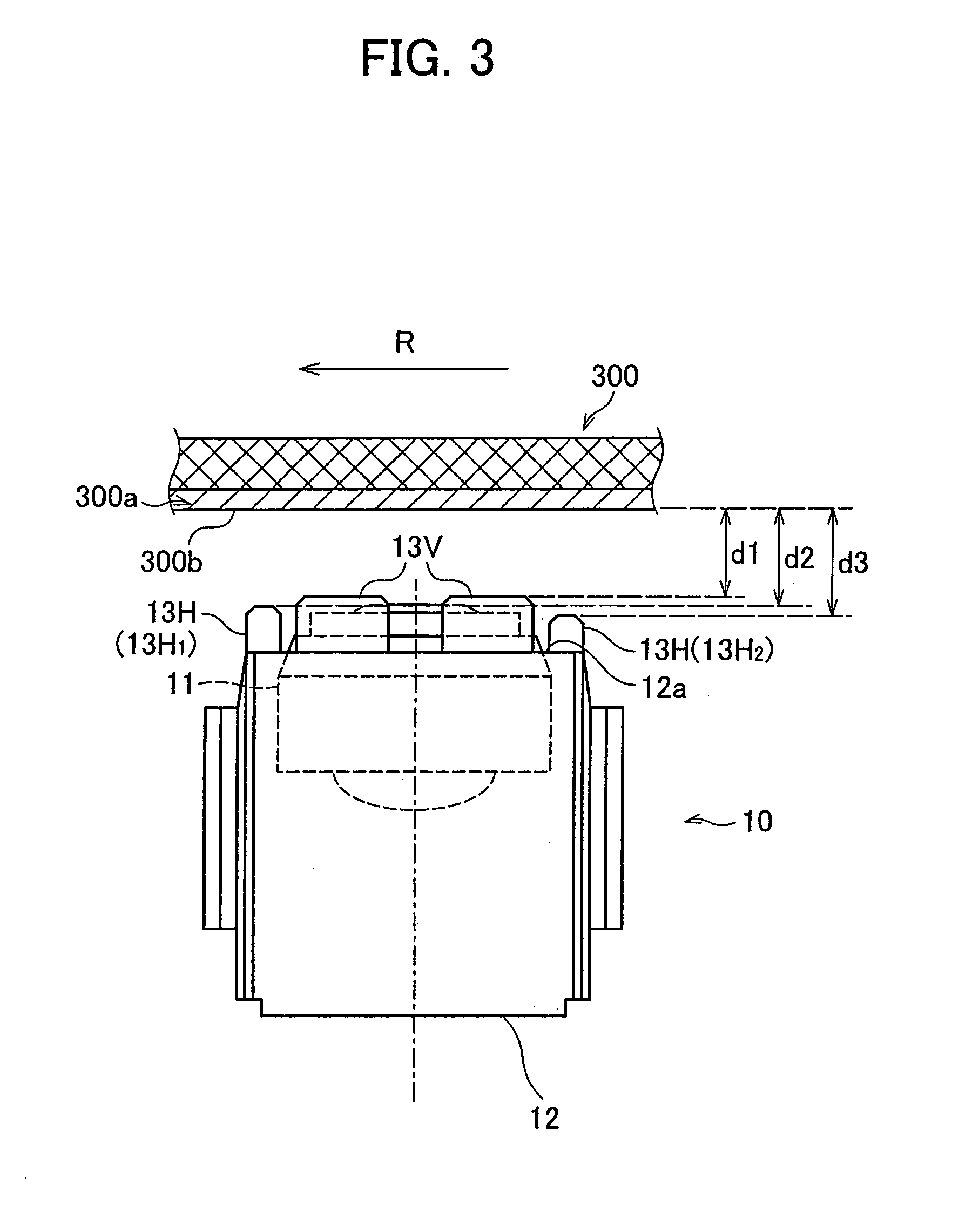
[0036] An embodiment of the present invention is explained as follows with reference to FIGS. 1 through 4(a) and 4(b). In this embodiment of the present invention, a lens holding system of an optical pick up device provided in a recording / reproducing device is given as an example for the explanation. The recording / reproducing device records and / or reproduces information by irradiating a beam of light on an optical disk which is caused to be in a rotating state.

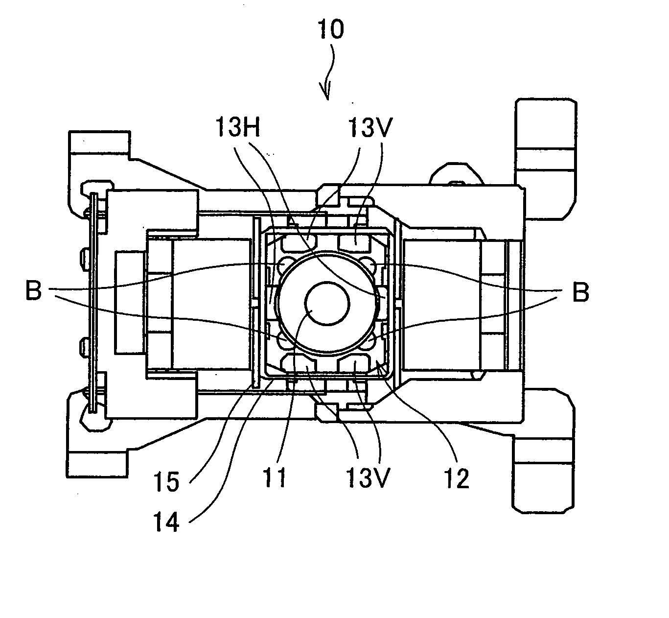
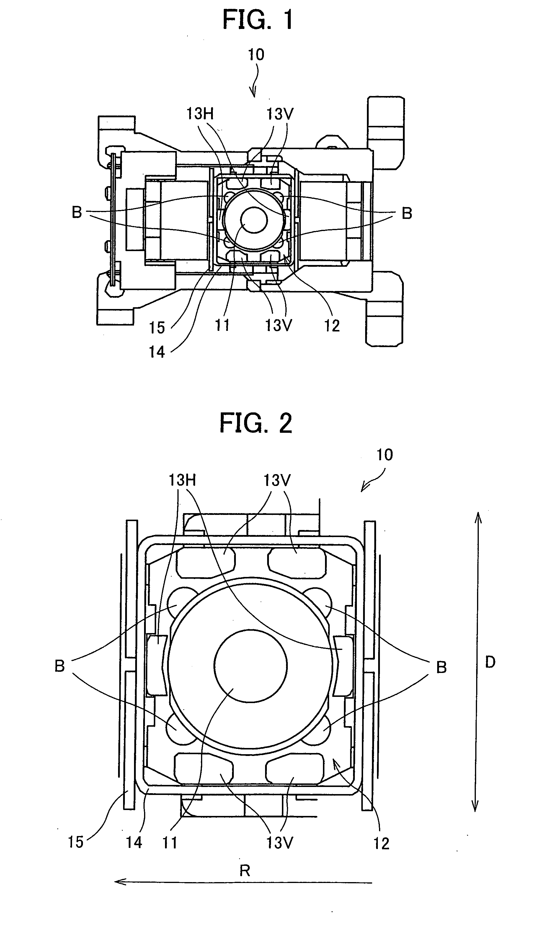
[0037]FIG. 1 illustrates a structure of a lens holding system 10 of this embodiment. Moreover, in FIG. 2, an area around the objective lens 11 of the lens holding system 10 more greatly magnified and illustrated. As illustrated in FIG. 1, the lens holding system 10 includes the objective lens 11, a lens holder (lens holding section) 12, plural lens protectors (lens protection sections) 13V and 13H, a focusing coil (driving section) 14 and a tracking coil (driving section) 15. The objective lens 11 converges a laser emitted fr...


PUM

PropertyMeasurementUnit
distanceaaaaaaaaaa
diameteraaaaaaaaaa
circular shapeaaaaaaaaaa

Abstract

In a lens holding system of the present invention, at least two lens protection sections protruding from a surface of a lens holding section are provided, which surface faces the optical recording medium, the lens protection sections sandwiching an objective lens therebetween. A distance between each of the lens protection sections and the optical recording medium is smaller than a distance between the objective lens and the optical recording medium. Accordingly, according to the structure mentioned above, because each of plural lens protection sections is independently provided, spaces between (i) adjacent lens protection sections and (ii) each of the lens protection sections and the lens holding section are easily formed. This makes it possible to easily perform attachment/detachment of the objective lens to/from the lens holding section. Further, a region for releasing heat is easily formed by the space provided between adjacent lens protection sections mentioned above. Therefore, it becomes possible to prevent temperature rise, caused by generation of heat in driving sections, of the objective lens and a region surrounding the objective lens.

Description

[0001] This Nonprovisional application claims priority under 35 U.S.C. §119(a) on Patent Application No. 347612 / 2004 filed in Japan on Nov. 30, 2004, the entire contents of which are hereby incorporated by reference. FIELD OF THE INVENTION [0002] The present invention relates to a lens holding system for holding an objective lens provided in an optical pick up device, the optical pick up device including this lens holding system, and a recording / reproducing device. BACKGROUND OF THE INVENTION [0003] Optical disks such as a CD-ROM (Compact Disk Read Only Memory), CD-R (Compact Disk Recordable), CD-RW (Compact Disk Rewritable), DVD-ROM (Digital Versatile Disk Read Only Memory), and DVD-RW (Digital Versatile Disk Rewritable) are, in general, widely used as information recording media having high capacity. In a disk drive device (which is also called a recording / reproducing device) for recording and / or reproducing information into / from these optical disks, an optical pick up for recordi...

Claims


Application Information

Patent Timeline
Patent Type & Authority Applications(United States)
IPC IPC(8): G11B7/00G02B7/02
CPCG11B7/1374G11B7/22
Inventor MASHIYAMA, TOMIONAKAMURA, MASAHIROINUI, TOSHIHARUTOMOYAMA, SHINICHI
Owner SHARP KK
Why Eureka
Try Eureka