
Protective eyewear

Active Publication Date: 2006-06-08
WM T BURNETT IP
View PDF16 Cites 16 Cited by
  • Summary
  • Abstract
  • Description
  • Claims
  • Application Information

AI Technical Summary

Benefits of technology

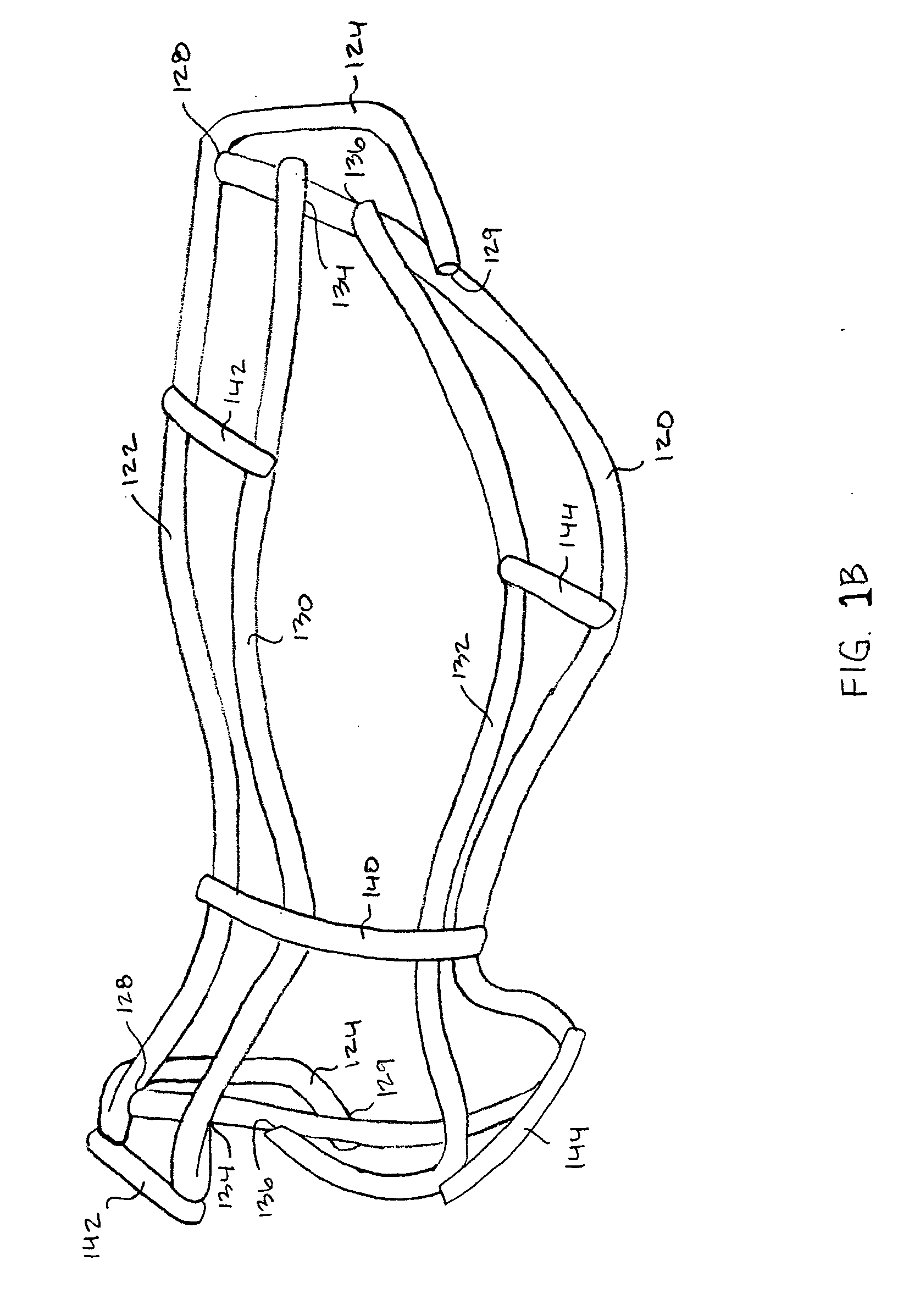
[0014] In an embodiment of the invention, the frame has only one vertical protective bar in the user's field of vision, located substantially over the nose of the user. By minimizing vertical members and strategically sizing, spacing, and locating the protective bars, the frame of the present invention defines a wide unobstructed viewing area that extends around the sides of the user's eyes. This unobstructed area maximizes the user's field of vision, in directions straight ahead, up and down, and peripherally. At the same time, the protective bars of the frame prevent a standard sized lacrosse ball from impacting a user's eye and enable the present invention to comply with generally accepted rules on the construction of protective eyewear, such as the requirements of ASTM F803-03, the Protective Eyewear Certification Council (PECC), U.S. Lacrosse, and the National Federation of High Schools (NFHS).

Problems solved by technology

In lacrosse, the hard, heavy rubber lacrosse ball can cause significant injury to unprotected eyes and faces.
Because the lacrosse balls are routinely thrown at high speeds and with great force, the impact of the balls can cause bruises, broken bones, and, in rare cases, even death.
Improvements in the strength of the equipment, however, often cause the equipment to be too stiff, bulky, or obtrusive, and uncomfortable to wear.
This discomfort can cause a player to wear the equipment improperly or not at all, thereby defeating any improvement in protection.

Method used


Image

  • Protective eyewear
  • Protective eyewear
  • Protective eyewear

Examples


Embodiment Construction

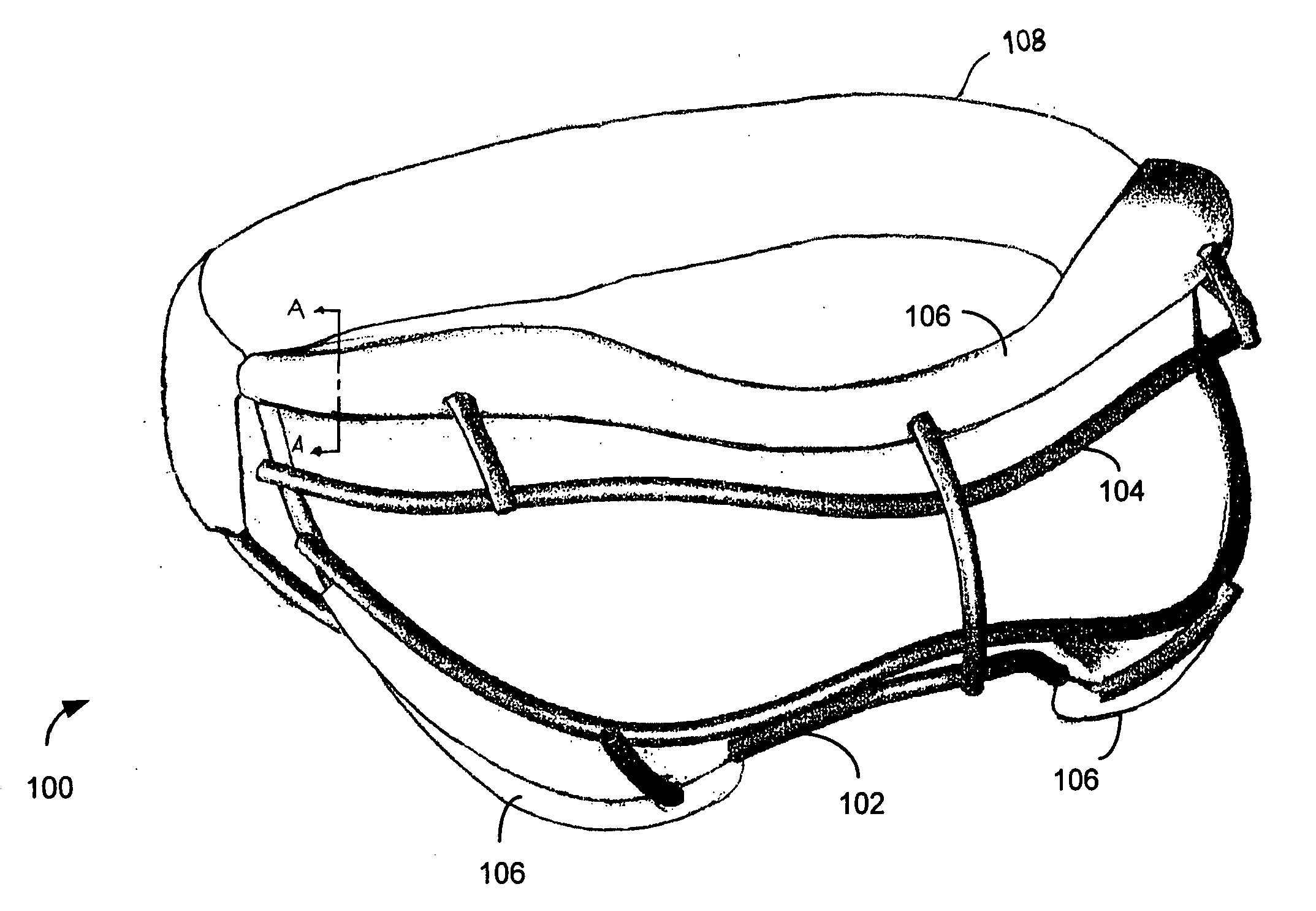
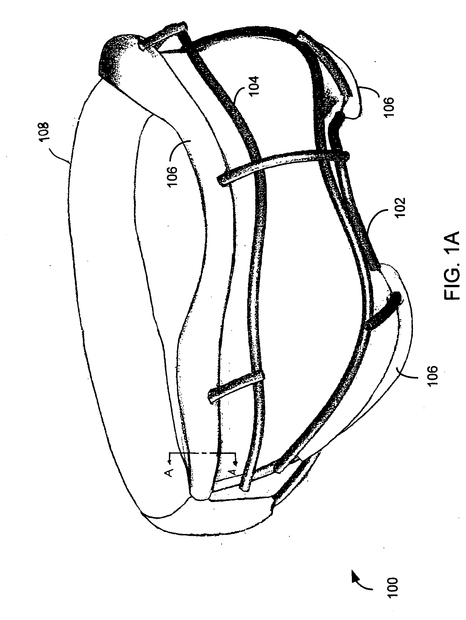
[0030]FIG. 1A is a schematic diagram of an isometric view of an exemplary protective eyewear apparatus 100, according to an embodiment of the present invention. As shown, eyewear apparatus 100 includes a base 102, a protective cage 104, compressible layers 106, and securing means 108. Base 102 and protective cage 104 provide the frame of eyewear apparatus 100 and can be made of weldable and bendable steel, such as 3.8 mm 1008 solid carbon steel wire, ASTM Standard, Section 03.05. Other suitable materials include other metals, metal alloys, composite materials, and synthetic materials. In this example, compressible layers 106 are disposed on base 102 in areas at which eyewear apparatus 100 contacts the face of a user, along the inferior forehead and the zygomatic arch (the temporal bone of the skull that forms the prominence of the cheek). Compressible layers 106 could be separate pieces located at each area of contact (e.g., forehead and zygomatic arch) of base 106 or could be one c...


PUM


Abstract

A protective eyewear apparatus including a base substantially oval in shape, an upper bar connected to the base, a lower bar connected to the base, and a main support bar connected to the upper bar and the lower bar. Another embodiment includes two eyepieces attached by a flexible bridge member, in which an eyepiece comprises a base generally oval in shape and defining an opening, and an upper and lower bar spanning the opening and connected to the base.

Description

BACKGROUND [0001] 1. Field of the Invention [0002] The present invention relates generally to protective eyewear, and more particularly, to a protective eyewear apparatus for sports such as women's lacrosse or field hockey. [0003] 2. Background of the Invention [0004] Protecting players from injury is a primary concern for any sport. The most vulnerable part of the body is the head, face, and eyes. Thus, protective face masks and eyewear are common in sports such as baseball, hockey, football, racquetball, squash, and lacrosse. [0005] In lacrosse, the hard, heavy rubber lacrosse ball can cause significant injury to unprotected eyes and faces. Most generally accepted rules for competitive lacrosse require a lacrosse ball made of solid rubber, between 7¾ and 8 inches in circumference (about 2 ½ inches in diameter), and between 5 and 5 1 / 4 ounces in weight. Because the lacrosse balls are routinely thrown at high speeds and with great force, the impact of the balls can cause bruises, b...

Claims


Application Information

Patent Timeline
IPC IPC(8): A41D13/00
CPCA42B3/20A61F9/02A63B71/10
Inventor HAHN, HELEN M.KOHLER, DALE W.
Owner WM T BURNETT IP
Learn More