
Coiler plate for sliver-coiling devices, especially of draw frames and carding machines

a technology of sliver coiling and coiling device, which is applied in the field of coiling coiling coiling device, can solve the problems of large amount of time required to close the gap space between the coiling coil and the rotary coil, and the cost of casting material, etc., and achieve the effect of low friction

Inactive Publication Date: 2006-06-08
TRUETZSCHLER GMBH & CO KG
View PDF11 Cites 2 Cited by
  • Summary
  • Abstract
  • Description
  • Claims
  • Application Information

AI Technical Summary

Benefits of technology

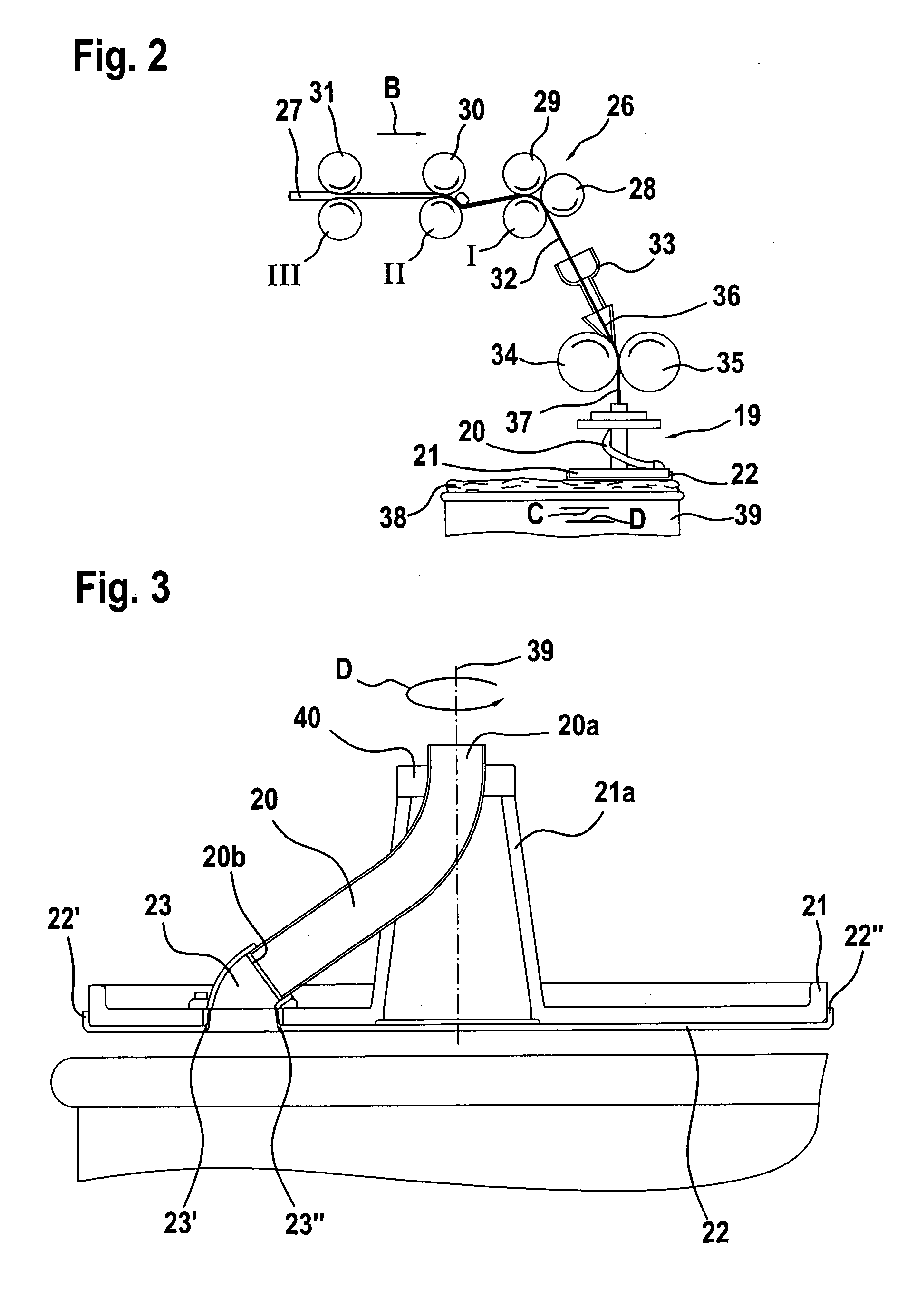
[0009] Because a connection piece having a through opening is formed with the cover, especially by a shaping step, the openings and the connecting element for the sliver channel outlet can be integrated into the cover. The opening, which may be, for example, approximately kidney-shaped, is advantageously produced from the sheet-form cover by non-cutting shaping, a clean transition being created between the flat cover surface and the contours of the opening, so that subsequent machining work is completely or largely unnecessary. In particular, there are no problems with adhering fibres or the like.

Problems solved by technology

A disadvantageous aspect is the considerable effort required in terms of manufacturing and assembly.
The casting material is expensive.
A further problem is the considerable amount of time required to close the gap space between the rotary plate and the sliver tube outlet.
Sharp edges and transitions require laborious polishing.

Method used


Image

  • Coiler plate for sliver-coiling devices, especially of draw frames and carding machines
  • Coiler plate for sliver-coiling devices, especially of draw frames and carding machines
  • Coiler plate for sliver-coiling devices, especially of draw frames and carding machines

Examples


Embodiment Construction

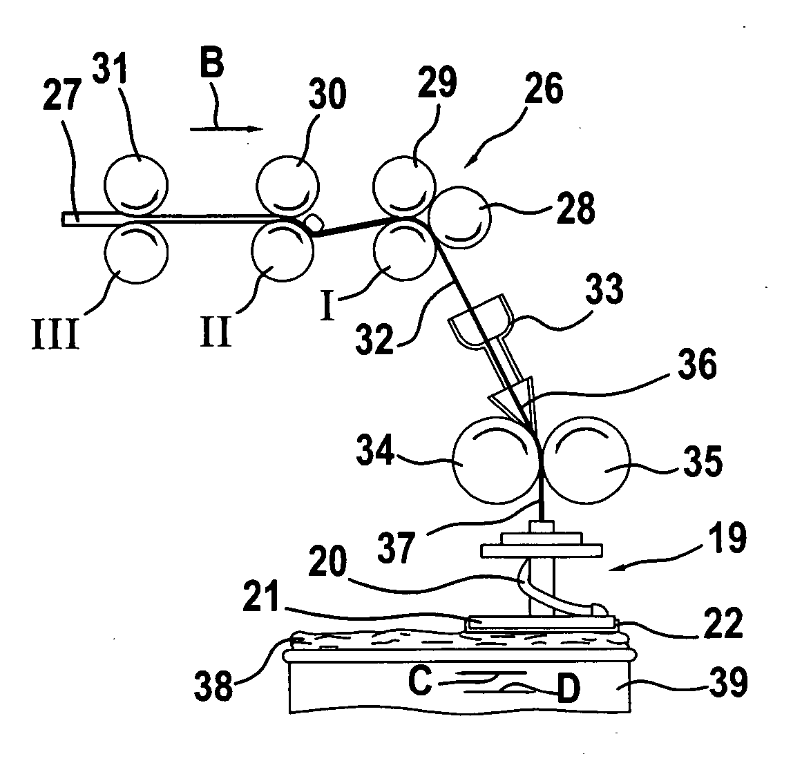
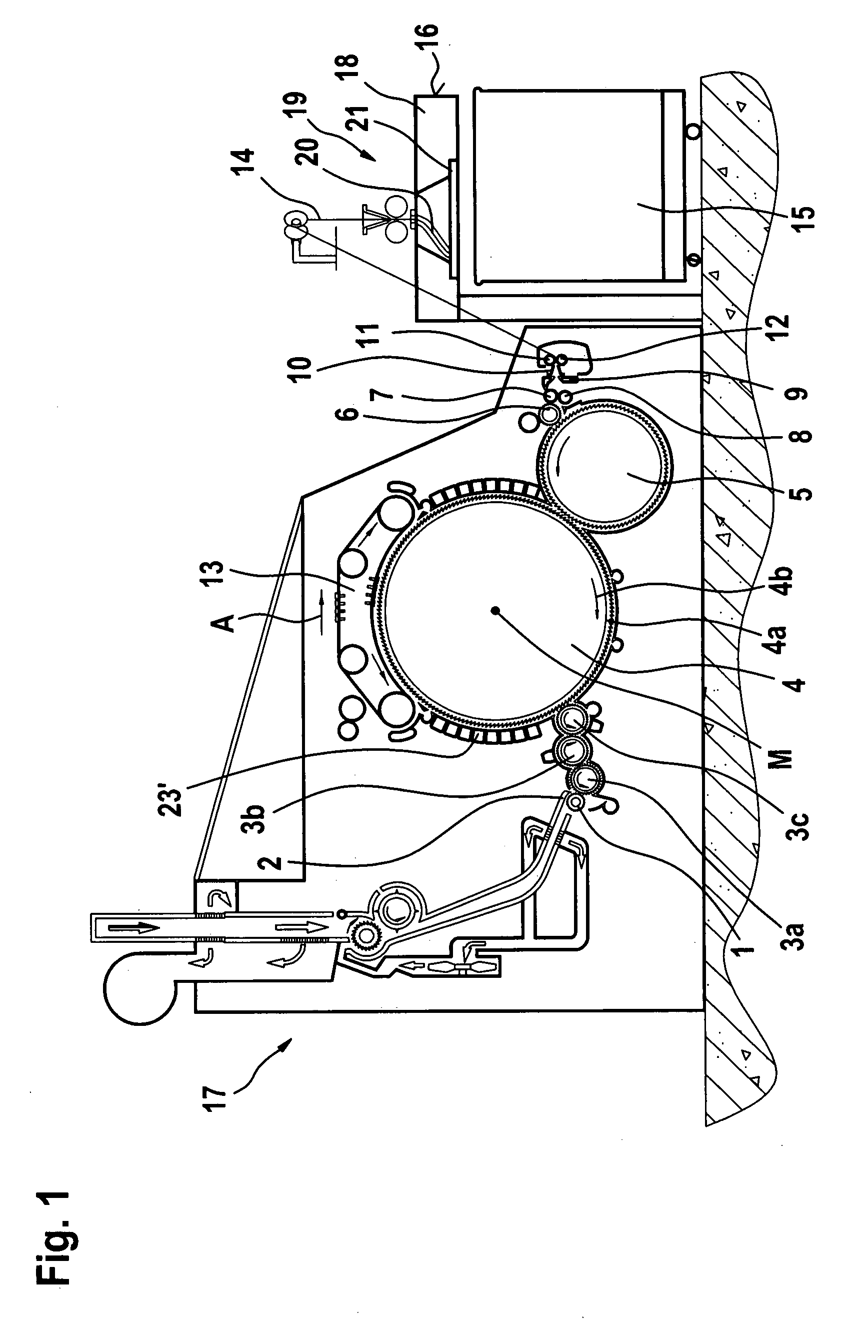
[0018]FIG. 1 shows a carding machine, for example a TC 03 (trademark) carding machine made by Trützschler GmbH & Co. KG of Mönchengladbach, Germany, having a feed roller 1, feed table 2, lickers-in 3a, 3b, 3c, cylinder 4, doffer 5, stripper roller 6, nip rollers 7, 8, web guide element 9, sliver funnel 10, delivery rollers 11, 12, revolving card top 13 with card top guide rollers and card top bars, can 15 and can coiler 16. The directions of rotation of the rollers are indicated by curved arrows. Reference letter M denotes the centre point (axis) of the cylinder 4. Reference numeral 4a indicates the clothing and reference numeral 4b indicates the direction of rotation of the cylinder 4. Arrow A denotes the operating direction. A flock feed device 17 is arranged upstream of the carding machine. The coiler plate 19 is rotatably mounted in the coiler plate panel 18. The coiler plate 19 comprises a sliver channel 20 with an inlet and an outlet (see FIG. 3) for sliver and a rotary plate ...


PUM

PropertyMeasurementUnit
frictionaaaaaaaaaa
diametersaaaaaaaaaa
internal diameteraaaaaaaaaa

Abstract

In a coiler plate for sliver-coiling devices, especially of draw frames and carding machines, having a sliver channel with an inlet and an outlet for sliver and having a rotary plate, there is present on the underside of the rotary plate a cover which has a through opening. In order to create a coiler plate in a simple manner, a connection piece having a through opening is formed integrally with the cover by deformation.

Description

CROSS REFERENCE TO RELATED APPLICATION [0001] This application claims priority from German Patent Application No. 10 2004 058 573.3 dated Dec. 3, 2004, the entire disclosure of which is incorporated herein by reference. BACKGROUND OF THE INVENTION [0002] The invention relates to a coiler plate for sliver-coiling devices, especially of draw frames and carding machines. [0003] In general, coiler plates have a sliver channel with an inlet and an outlet for sliver and a rotary plate, there being present on the underside of the rotary plate a cover which has a through opening. In a known coiler plate (EP-A-0 670 281), a round tube, as starting material, is formed by shaping to form a three-dimensionally curved sliver channel. In the semi-finished product, the outlet bend is followed by a straight portion which is separated during completion of the sliver channel. The outlet of the sliver channel is so constructed that it terminates level with the base of the rotary plate. The base of the...

Claims


Application Information

Patent Timeline
Patent Type & Authority Applications(United States)
IPC IPC(8): D04H11/00D01G99/00
CPCB65H54/80B65H2701/31
Inventor KRANEFELD, ANDREASLANDMESSER, THOMAS
Owner TRUETZSCHLER GMBH & CO KG
Learn More