

Plain journal bearing
- Summary
- Abstract
- Description
- Claims
- Application Information
AI Technical Summary
Benefits of technology
Problems solved by technology
Method used
Image

Examples
first embodiment
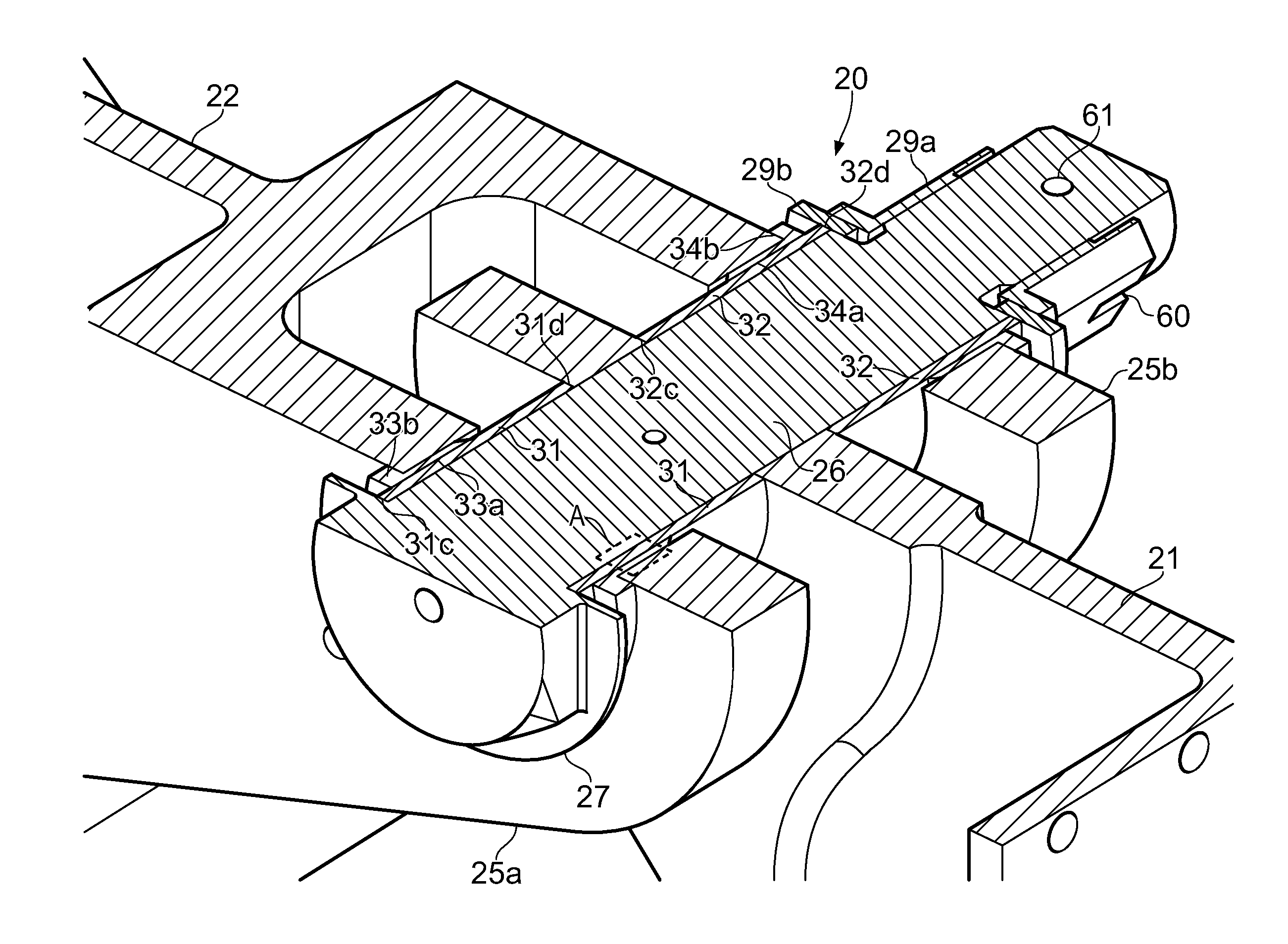
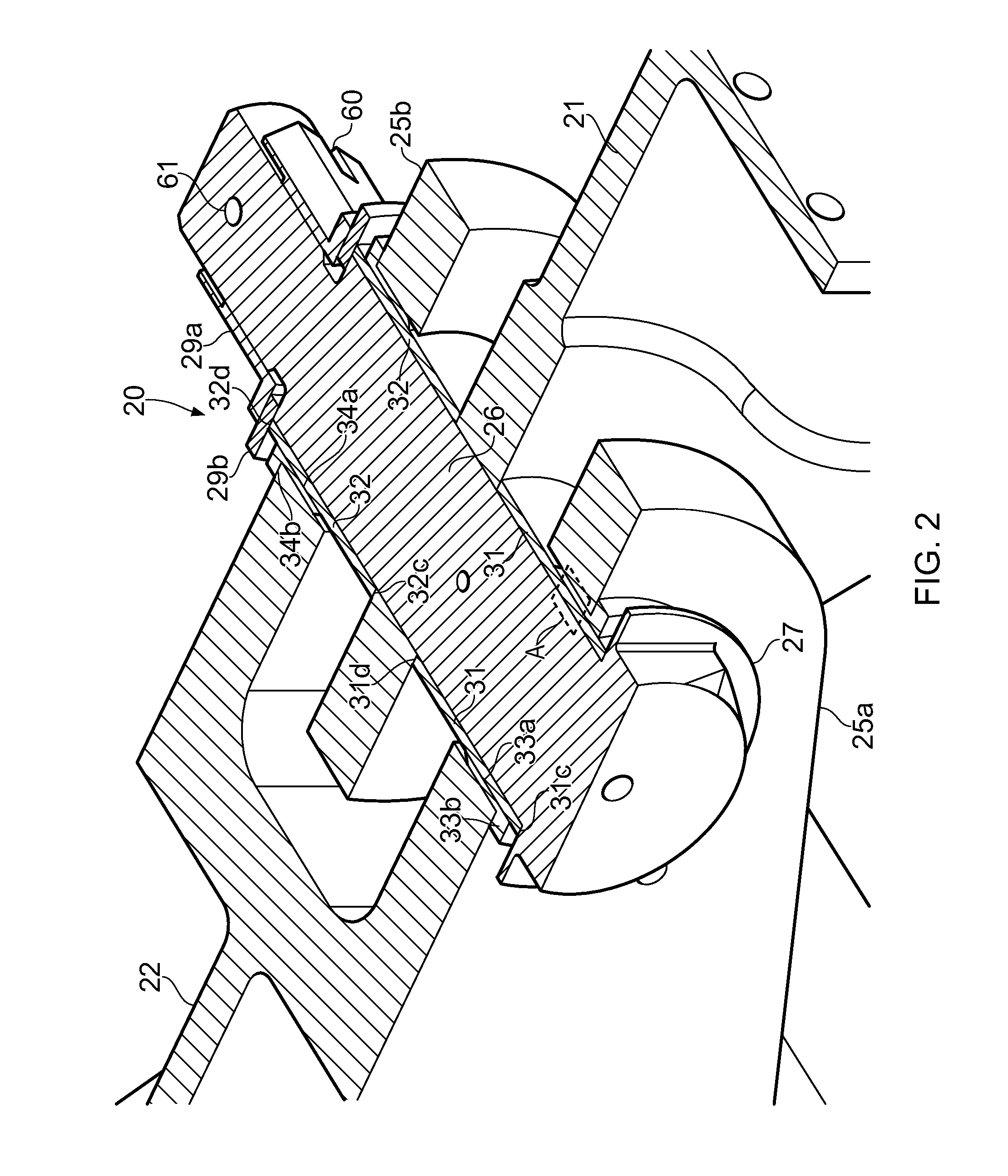
[0027]FIG. 3 is an enlarged view of a small area A in FIG. 2 according to the invention. In this example the shaft 26 and clamping bush 31 are formed from low friction materials which do not require low friction coatings. For example the shaft 26 may be made from corrosion-resistant steel and the clamping bush 31 may be made from Aluminium bronze.
second embodiment
[0028]FIG. 4 is an enlarged view of the area A in FIG. 2 according to the invention. In this example a low friction coating 40 is adhered to the outer diameter of the shaft 26, and similarly a low friction coating 41 is adhered to the outer diameter of the clamping bush 31. Alternatively the coating 41 may be adhered to the inner diameter of the clamping bush 31 instead of being adhered to the shaft 26 of the pin. The other clamping bush 32 in this embodiment is also provided with a similar low friction coating on its outer diameter (and optionally also its inner diameter).
[0029]The coatings 40, 41 are formed from a material with a lower coefficient of friction than the pin, the clamping bush, and the fixed bush. Examples of suitable low friction materials are PTFE or other polymer based materials; molybednum disulphide; Zincnickel, Cadmium, or chrome. The coatings may be applied as a paste and then cured and machined; sprayed on with an evaporating carrier; or applied by magnetron ...
PUM
| Property | Measurement | Unit |
|---|---|---|
| Diameter | aaaaa | aaaaa |
| Friction | aaaaa | aaaaa |
Abstract
Description
Claims
Application Information