
Slim-line casing centralizer

a centralizer and slim-line technology, applied in the direction of drilling casings, drilling pipes, drilling rods, etc., can solve the problems of reducing the capacity requiring greater pumping. , to achieve the effect of reducing reducing the amount of side load support, and increasing the capacity of expansion and collaps

Inactive Publication Date: 2015-05-14
WWT NORTH AMERICA HLDG
View PDF3 Cites 3 Cited by
  • Summary
  • Abstract
  • Description
  • Claims
  • Application Information

AI Technical Summary

Benefits of technology

The present invention is a slim-line casing centralizer that has limited expansion and collapse capability but provides high amounts of side load support. The centralizer includes three components: a top and bottom stop collar and a centralizer sleeve. The centralizer body is made of steel or a high-strength metal and consists of a multiplicity of support fingers that are shaped to support a predetermined load at their apex. The centralizer can experience radial loads and the support fingers collapses into a pocket to guide the spring finger into its collapse without interference with the body of the centralizer. The technical effects of the invention are improved stability and support for the casing during drilling and wellbore construction.

Problems solved by technology

Historically, many different attempts were made to satisfy the multiple requirements for proper casing centralization; but these have failed because only one or two of the performance requirements were satisfied in previous designs.
This centralization is difficult because of well bore configuration and common drilling problems.
If the centralizer fills a significant portion of the annulus between the casing and the well bore, the result is restriction of the cement flow, thus requiring greater pumping, but more incomplete cement coverage.
Another common problem occurs when running a smaller casing liner through a casing exit without a whipstock in place.
For these applications, failure of the centralizers run on liners through casing exits can result in expensive time lost due to fishing (retrieving parts) and milling of pieces of centralizers in order to obtain proper well function.
This significant problem is associated with the transition across the sharp edge of the casing and into open hole.
Further, existing bow-type centralizers do not provide enough side load support, and hence when used will collapse, thus not providing a centralized pipe and may result in a poor or even unsafe cement bond between the casing and the formation.
Hence, there exists a need for a centralizer with limited expansion and collapse capability but with high amounts of side load support capability.

Method used


Image

  • Slim-line casing centralizer
  • Slim-line casing centralizer
  • Slim-line casing centralizer

Examples


Embodiment Construction

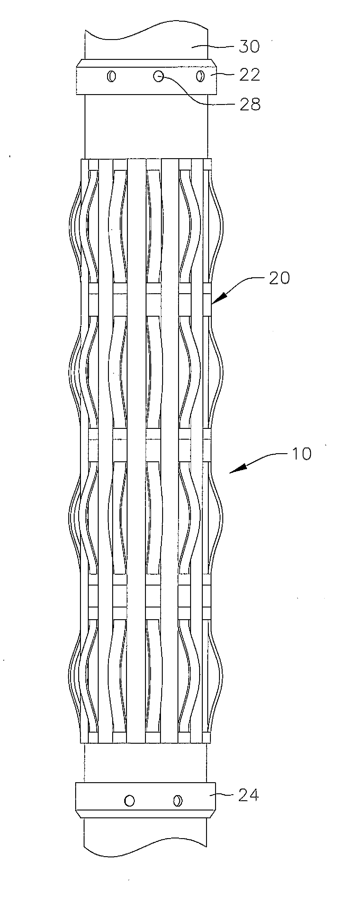
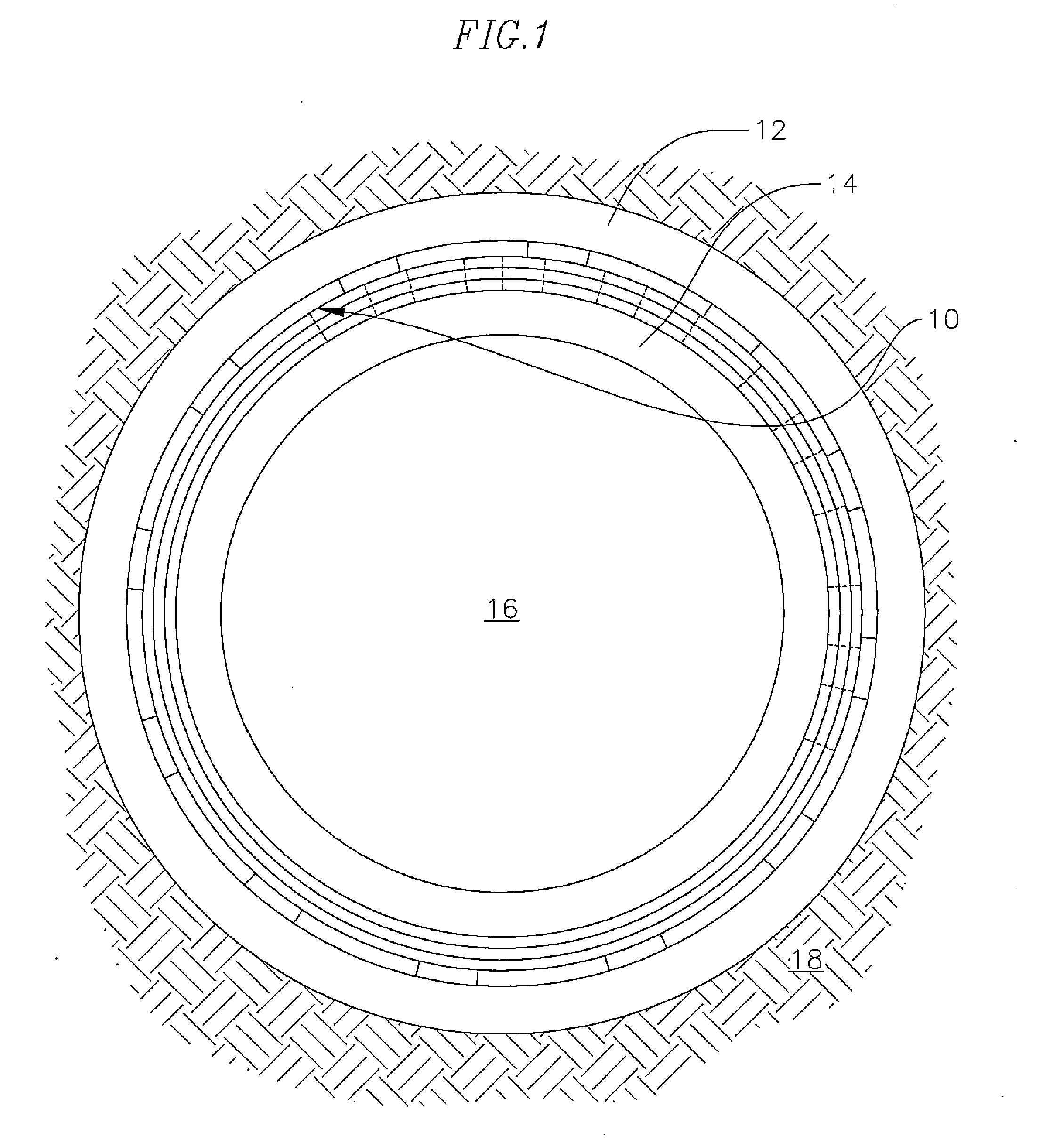
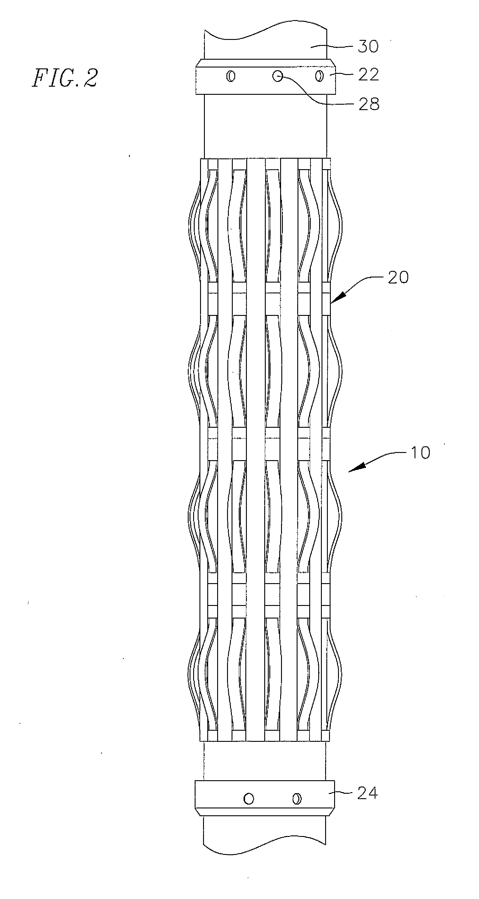
[0016]FIG. 1 is a cross sectional view of a slim-line casing centralizer 10 positioned in the narrow annular space between casings 12 and 14 located within a bore hole 16 drilled within an underground formation 18. As shown in FIG. 2, the casing centralizer 10 consists of a centralizer sleeve 20 and top and bottom stop collars 22 and 24. As also shown in FIG. 3, stop collars are typically made of steel or aluminum or other metal and include holes 26 for the insertion of steel set screws 28 which when turned apply a griping force from the collar to the inner casing 14.

[0017]As also can be seen in FIG. 4, the centralizer body or sleeve 20 is typically made of a sheet of steel that is quenched and tempered to produce a high strength spring-steel-like behavior. Alternatively, the centralizer body can be made of a low modulus high strength metal such as titanium or a specially designed fiber-epoxy composite.

[0018]The centralizer body can include a coating of low friction materials to pre...


PUM


Abstract

A casing centralizer having a multiplicity of support fingers positioned on a body of the casing centralizer each finger formed into a collapsible spring configured to support a predetermined load at an apex of the finger, each finger having a leading forward angle positioned downhole and a following aft angle positioned uphold and a landing tab positioned on an end of the finger adjacent the aft angle, the body includes a finger pocket which guides the landing tab with the finger collapses due to side loads.

Description

CROSS-REFERENCE TO RELATED APPLICATION(S)[0001]This application claims the benefit of and priority to U.S. Provisional Application No. 61 / 902,091, filed Nov. 8, 2013, the contents of which are incorporated herein in its entirety.FIELD OF THE INVENTION[0002]This invention relates to gas and oil production, and more particularly to improvements in casing centralization.BACKGROUND[0003]To obtain pressure integrity and structural adequacy, typically after an oil or gas well is drilled the hole is lined with steel pipe and cement is inserted between the pipe and the formation. The centering of the casing within the hole is performed by casing centralizers of various types. Many casing centralizer types exist including fixed diameter solid cast or molded types with various types of thin-like extensions such as cords or spiral-shaped, bow-spring types that are self or double bow with welded and non-welded bows made of various material including zinc, steel, and plastic.[0004]Casing central...

Claims


Application Information

Patent Timeline
Patent Type & Authority Applications(United States)
IPC IPC(8): E21B17/10E21B17/00
CPCE21B17/00E21B17/1078E21B17/1028
Inventor MOORE, NORMAN BRUCEMITCHELL, SARAH
Owner WWT NORTH AMERICA HLDG
Learn More