Low compliant catheter tubing

a low-compliant, catheter-based technology, applied in the field of intravascular catheters, can solve the problems of lagging compliance, affecting the operation efficiency of the catheter, and lagging flexibility, etc., and achieves the effects of reducing the density, reducing the modulus, and improving the complian

Active Publication Date: 2011-12-06
ABBOTT CARDIOVASCULAR
View PDF93 Cites 26 Cited by
  • Summary
  • Abstract
  • Description
  • Claims
  • Application Information

AI Technical Summary

Benefits of technology

[0009]The low hardness polyamide or copolyamide is typically semi-crystalline having crystalline region and amorphous region. The amorphous region generally has a lower density than the crystalline region and generally has lower modulus, resulting in higher compliance in the amorphous region compared to crystalline region. This higher compliance in the amorphous region affects the overall modulus of the material and causes the material to be more compliant. If amorphous region can be reinforced by a higher modulus compatible material, the overall strength and modulus can be increased and compliance can be decreased. The present invention creates a balloon where the amorphous region of the lower durometer polyamide or copolyamide is reinforced by adding small amounts of a higher modulus amorphous material, thereby delaying the response of the amorphous region and increasing the overall modulus and strength of the material.
[0013]The balloon catheter of the invention has improved performance due to the flexibility, strength, and controlled expansion (compliance) of the balloon. The polymeric blend provides the surprising result of a balloon having a low compliance, for controlled balloon expansion, and having relatively high flexibility and softness, for excellent ability to track the patient's vasculature and cross lesions. These and other advantages of the invention will become more apparent from the following detailed description of the invention and the accompanying exemplary drawings.

Problems solved by technology

However, noncompliant balloons generally have relatively low flexibility and softness, making it more difficult to maneuver through various body lumens.
Heretofore the art has lacked an optimum combination of strength, flexibility, and compliance, and particularly a low to non-compliant balloon with high flexibility and softness for enhanced trackability.

Method used


Image

  • Low compliant catheter tubing
  • Low compliant catheter tubing
  • Low compliant catheter tubing

Examples


example 1

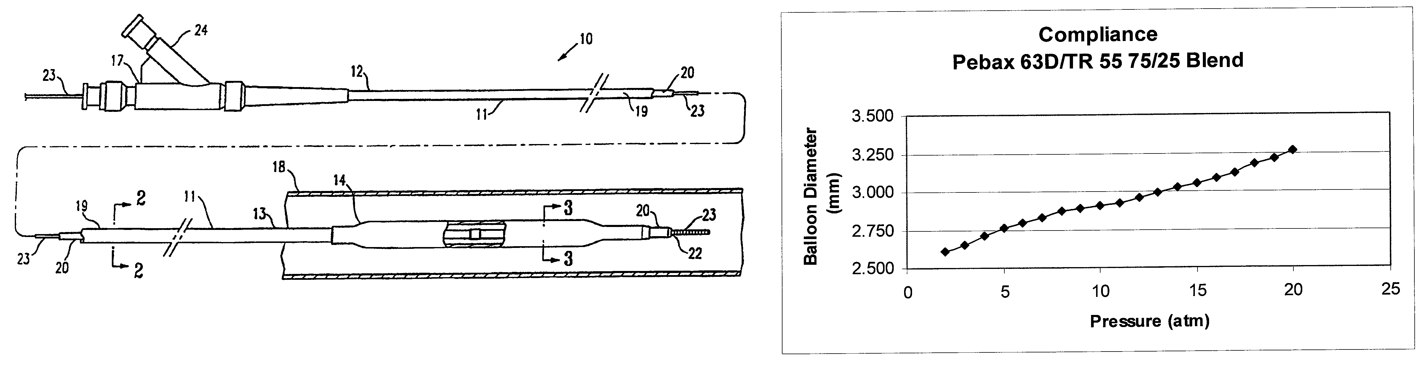
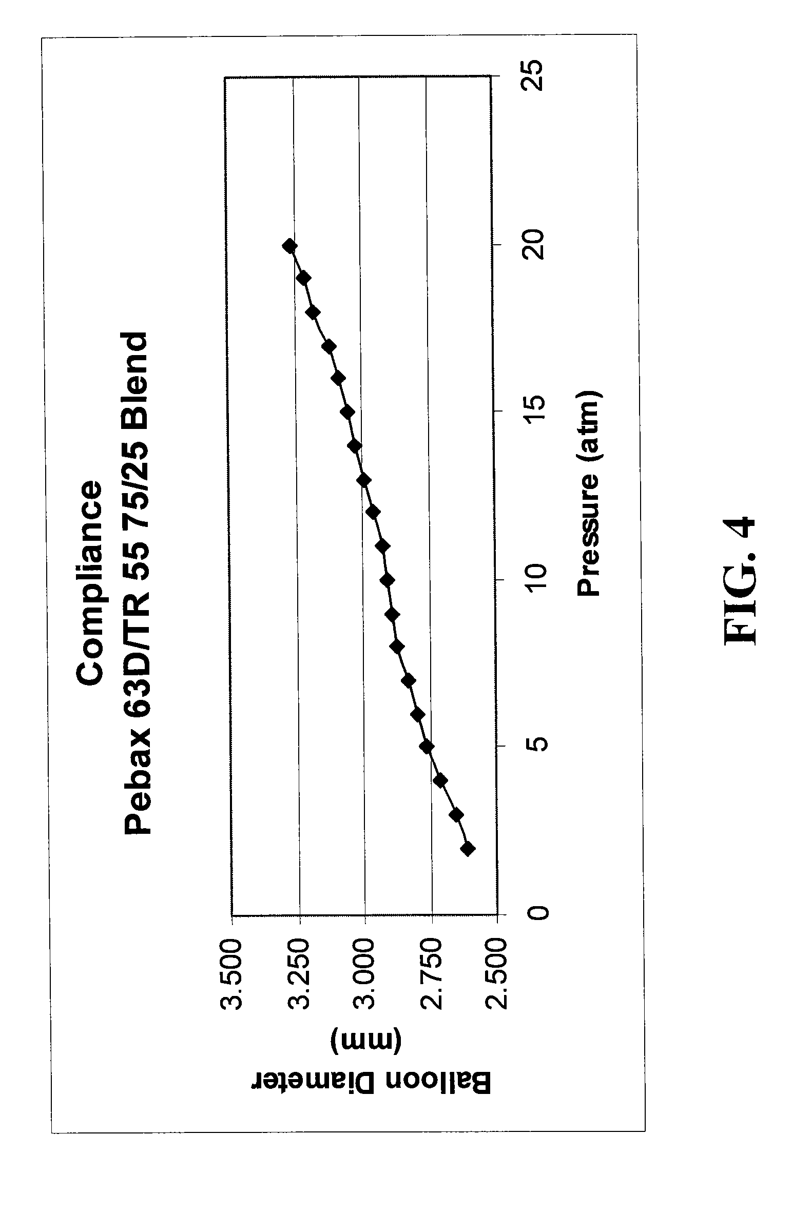
[0030]A blended composition of 75% Pebax 63D and 25% EMS TR 55 (transparent amorphous nylon) was constructed into ten sample catheter balloons according to the present invention, which produced an average working pressure range of eight to nine atmospheres for a 2.75 mm balloon. At five atmospheres, the balloon is about 2.75 mm (nominal diameter) and at thirteen atmospheres the balloon has grown radially roughly 0.25 mm to 3.00 mm (quarter size diameter). As shown in FIG. 4, this results in a compliance performance that is flatter in the operating range of the balloon, a desired characteristic. The balloon in Example 1 has a compliance of about 0.023 mm / atm between 5 atmospheres and 18 atmospheres, i.e., from nominal to the rated burst pressure of the balloon, where the nominal pressure is the pressure required to expand the balloon to its working diameter, and the rated burst pressure, calculated from the average rupture pressure, is the pressure at which 95% of the balloons can be...


PUM

PropertyMeasurementUnit
pressureaaaaaaaaaa
flexural modulusaaaaaaaaaa

Abstract

Balloon catheter comprises a shaft having a proximal end, a distal end, and an inflation lumen extending therein, and a balloon on the shaft which has an interior in fluid communication with the inflation lumen. The balloon is formed of a blend of polymeric materials comprising a transparent amorphous nylon having a Shore D duromcter hardness of not less than 77D and being not more than about 40% by weight of the blend, and a polyamide or a polyether block amide having a Shore D duromcter hardness of no more than 73D. An increase in radial diameter of the balloon above nominal pressure for one atmosphere of pressure is no greater than 0.025 mm / atm. A guidewire catheter is also provided.

Description

BACKGROUND[0001]The invention relates to the field of intravascular catheters, and more particularly to a balloon catheter or other catheter component, such as a guidewire enclosure, that would benefit from the properties of the materials disclosed herein.[0002]In percutaneous transluminal coronary angioplasty (PTCA) procedures, a guiding catheter is advanced until the distal tip of the guiding catheter is seated in the ostium of a desired coronary artery. A guidewire, positioned within an inner lumen of an dilatation catheter, is first advanced out of the distal end of the guiding catheter into the patient's coronary artery until the distal end of the guidewire crosses a lesion to be dilated. Then the dilatation catheter having an inflatable balloon on the distal portion thereof is advanced into the patient's coronary anatomy, over the previously introduced guidewire, until the balloon of the dilatation catheter is properly positioned across the lesion. Once properly positioned, th...

Claims


Application Information

Patent Timeline
Patent Type & Authority Patents(United States)
IPC IPC(8): A61M29/00A61M37/00A61F2/958
CPCA61L29/049C08L77/00
Inventor LEE, JEONG S.
Owner ABBOTT CARDIOVASCULAR
Why Eureka
Try Eureka