
Proxy for video on demand server control

Inactive Publication Date: 2006-05-04
MICROSOFT TECH LICENSING LLC
View PDF99 Cites 26 Cited by
  • Summary
  • Abstract
  • Description
  • Claims
  • Application Information

AI Technical Summary

Benefits of technology

[0008] The popularity of the Internet, a well-known, global network of cooperative interconnected computer networks, combined with the widespread availability of low-cost broadband networking and advanced digital compression techniques, has spurred the growth of what is known as interactive television. Interactive television provides viewers with compelling Internet and video content on their home television equipped only with a simple internet-television terminal, such as those pioneered by WebTV Networks, Inc. WebTV terminals are akin to the set-top boxes associated with a cable television network, and work in conjunction with a standard home television set to display both Internet and traditional television content, so that persons without access to a personal computer are able to access the Internet.
[0014] Current video-on-demand servers use a limiting “segmented channel” model to transmit the video data. Under this model, each viewer is assigned a dedicated video channel. This greatly limits flexibility and expansion options.
[0016] According to one aspect, the invention provides an improved system and method for delivering a video-on-demand feature to remote clients of an interactive television network. The system and method employ the proxy server to reconfigure the components of a video-on-demand application into a flexible multi-tiered configuration, and to redistribute the functions of those components to the proxy server so as to enhance the performance, reliability, security, scalability and other features of the system.

Problems solved by technology

One of the difficulties with the proliferation of competing video-on-demand applications is the lack of an industry standard communications protocol.
The challenge in a video-on-demand application is that it must be capable of managing not only the download of digital video data to the client, but also the transmission of control data to and from the client relating to system administration (e.g. channel assignment data, billing information, etc.).
Problems arise when the protocols used to control the video-on-demand servers aren't understood (are incompatible with) the protocols supported by the various video-on-demand clients.
The use of incompatible protocols has limited expansion options available to existing video on demand systems.
Moreover, the current configuration of most interactive video systems provide incomplete failover recoverability since the back-end servers on which most video-on-demand servers reside necessarily cannot completely manage their own failure.
This greatly limits flexibility and expansion options.

Method used


Image

  • Proxy for video on demand server control
  • Proxy for video on demand server control
  • Proxy for video on demand server control

Examples


Embodiment Construction

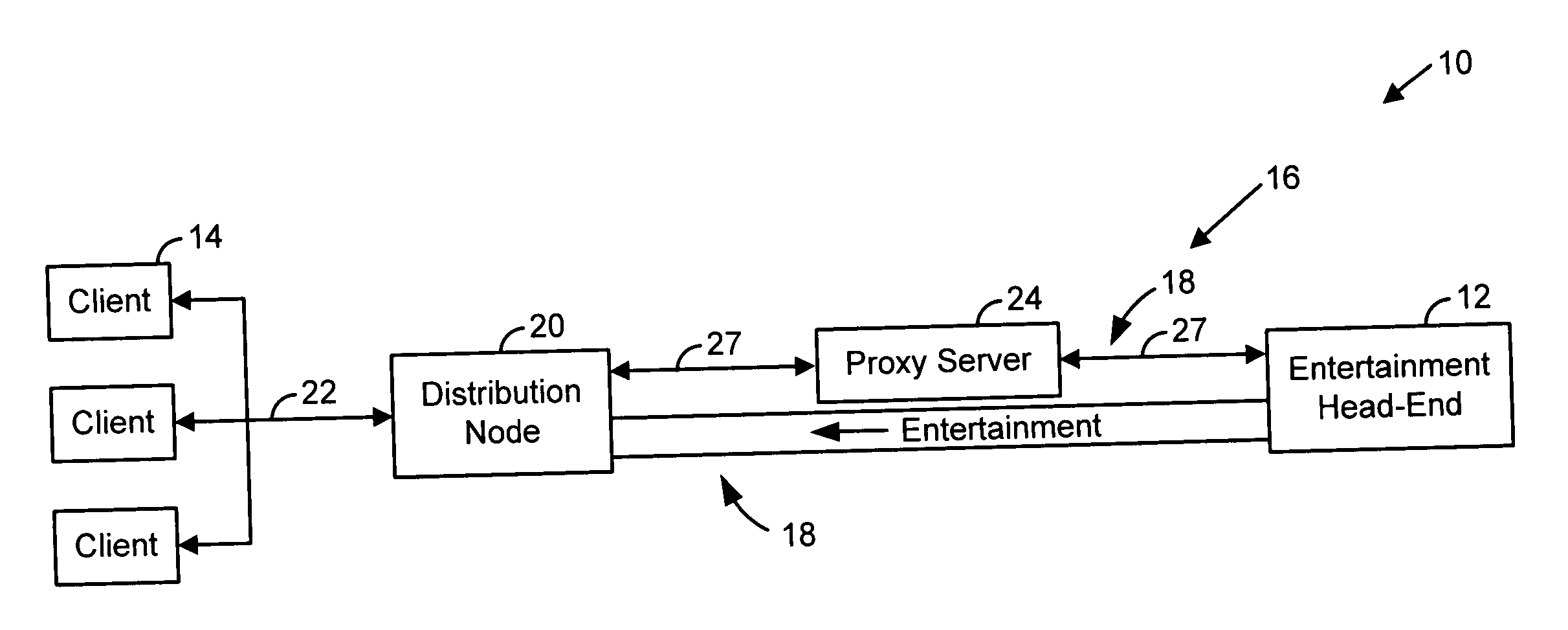
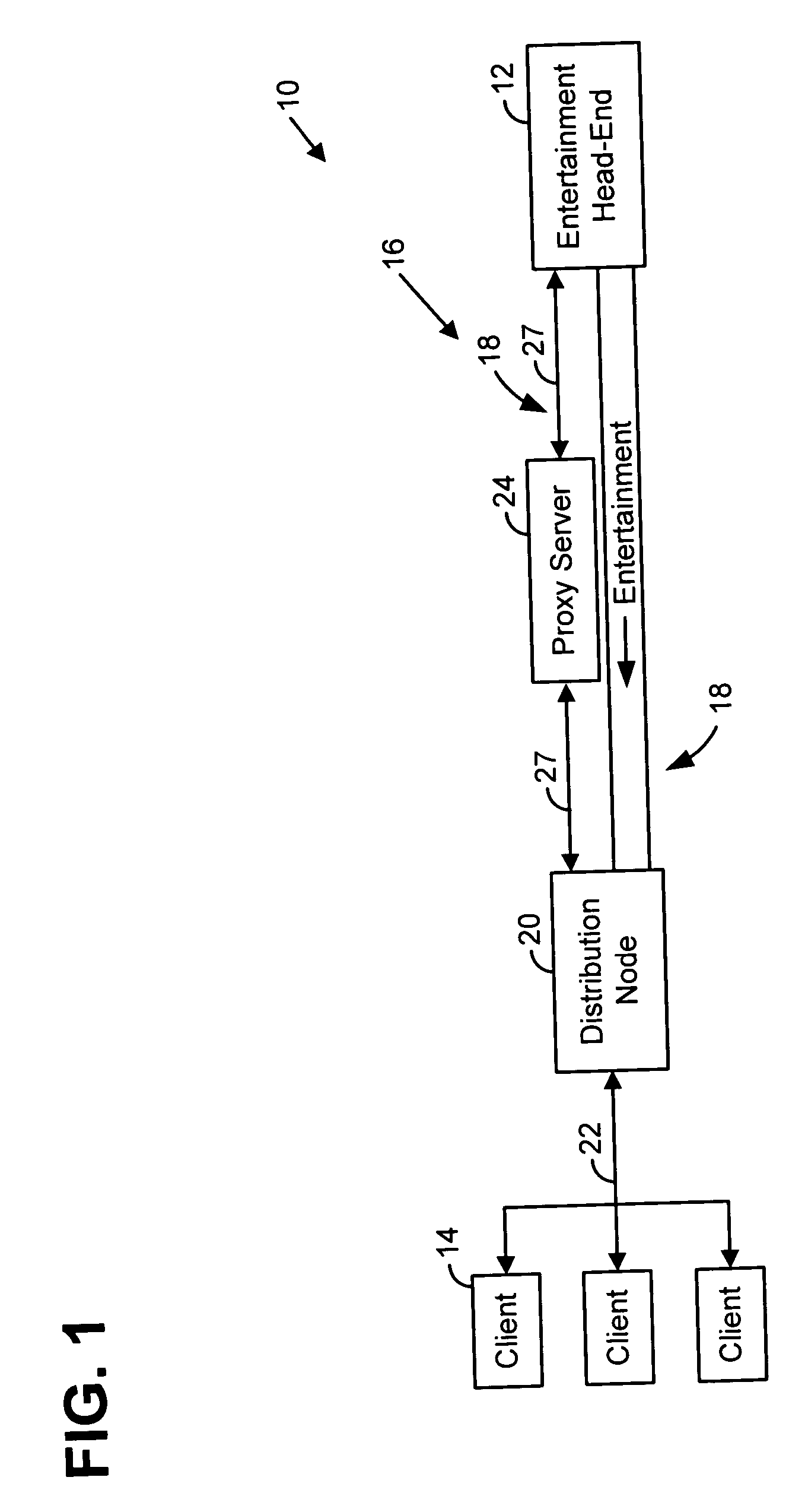
[0026] Referring to FIG. 1, an exemplary interactive entertainment system 10 according to one embodiment of the present invention includes an entertainment head-end 12, one or more proxy servers 24, and one or more client terminals 14 intercoupled through a network 16. The proxy servers 24 are computers interposed in a middle tier between the head-end 12 and the client terminals 14 to perform various interactive video system control and user interface (UI) functions.

[0027] The network 16 typically comprises coaxial cable or optical fiber 18, extending from the head-end 12 to distribution nodes 20 within various neighborhoods. From the distribution nodes, further cables 22 couple to individual subscriber premises.

[0028] The proxy server 24 is interposed in a logical TCP / IP control channel 27 between the head-end and clients. While the control signals and the entertainment are physically conveyed on the same cable 18, they are shown separately in FIG. 1 for conceptual clarity.

[0029...


PUM


Abstract

A video on demand system includes a head-end coupled through a proxy server to plural client terminals. The proxy server performs (or cooperates with another component in performing) various functions, including user interface definition, security, system administration (e.g. channel management, load distribution, and failover), and protocol translation.

Description

RELATED APPLICATION DATA [0001] The subject matter of this application is generally related to that disclosed in the following applications filed contemporaneously herewith: [0002] Video on Demand Methods and Systems (White et al); [0003] Method and System for Presenting Television Programming and Interactive Entertainment (White et al); and [0004] Interactive Video Programming Methods (White et al). [0005] The subject matter of this application is also generally related to the subject matter of application Ser. No. 09 / 153,577, filed Sep. 15, 1998. [0006] The disclosures of these related applications are incorporated by reference.FIELD OF THE INVENTION [0007] The present invention relates generally to interactive entertainment systems, and more particularly relates to the use of a processor between the head-end and the clients, to which various processing tasks can advantageously be delegated. BACKGROUND AND SUMMARY OF THE INVENTION [0008] The popularity of the Internet, a well-know...

Claims


Application Information

Patent Timeline
IPC IPC(8): H04N7/173H04L12/24H04L29/06H04L29/08H04N5/00
CPCH04L41/0896H04L63/02H04N7/17336H04N21/222H04N21/2225H04N21/23103H04N21/2405H04N21/4312H04N21/4314H04N21/47202H04N21/6118H04N21/6168H04N21/64707H04N21/6547H04N21/6587H04L65/104H04L65/4084H04L69/08H04L65/612
Inventor CARPENTER, J. WILTSEBRUCK, TIMOMIGHDOLL, LEE S.GOLDMAN, PHILLIP Y.
Owner MICROSOFT TECH LICENSING LLC
Learn More