Masonry cavity wall and method of assembly

Active Publication Date: 2006-06-08
BENJAMIN OBDIKE
View PDF35 Cites 21 Cited by
  • Summary
  • Abstract
  • Description
  • Claims
  • Application Information

AI Technical Summary

Benefits of technology

[0007] More specifically, the present invention provides a method of assembling a cavity wall with a debris blocker. A base section of a masonry wall is assembled adjacent an inner wall such that a wall cavity is defined therebetween, and a continuous, elongate strip of material is inserted within the wall cavity such that the strip of material is supported on a bottom surface of the wall cavity and forms a debris collection surface a spaced distance above the bottom surface of the wall cavity.

Problems solved by technology

Excess mortar and other building construction debris often falls within the ca

Method used


Image

  • Masonry cavity wall and method of assembly
  • Masonry cavity wall and method of assembly
  • Masonry cavity wall and method of assembly

Examples


first embodiment

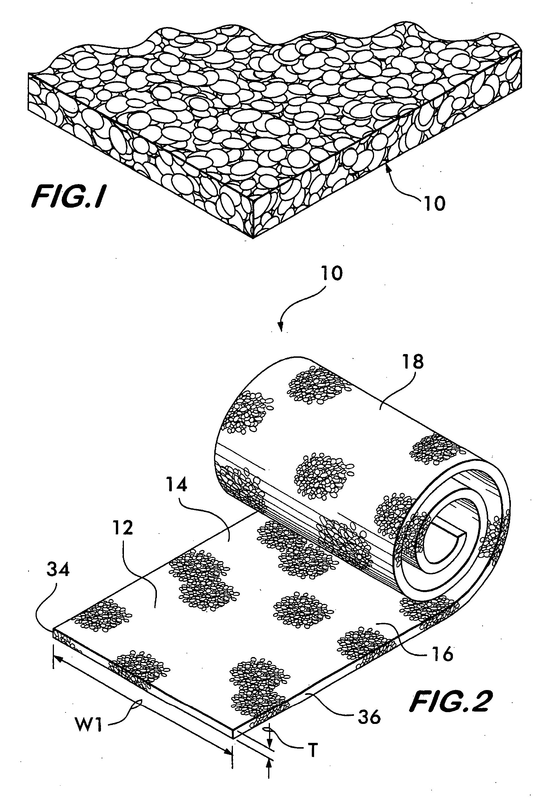
[0022] In the present invention illustrated in FIGS. 1-5, the blocker 10 is provided as a relatively-flat strip of material having a width “W1” (as measured in a flat condition) greater than a width “W2” of the wall cavity in which it is to be installed. The strip of material 10 is sufficiently flexible at least along a longitudinally-extending central section 12 thereof to permit the normally flat strip 10 to be inserted within the cavity in a bowed or inverted U-shape across its width. Thus, a pair of longitudinally-extending side sections, 14 and 16, of the strip 10 engage opposed wall surfaces that define the cavity, and the longitudinally-extending central section 12 forms an upwardly-projecting, debris-collection canopy therebetween that bridges the opposed walls.

[0023] The blocker 10 possesses a degree of resiliency such that, when flexed or folded along its longitudinally-extending central section 12, the strip exerts a force to expand to its normal relatively-flat condition...

second embodiment

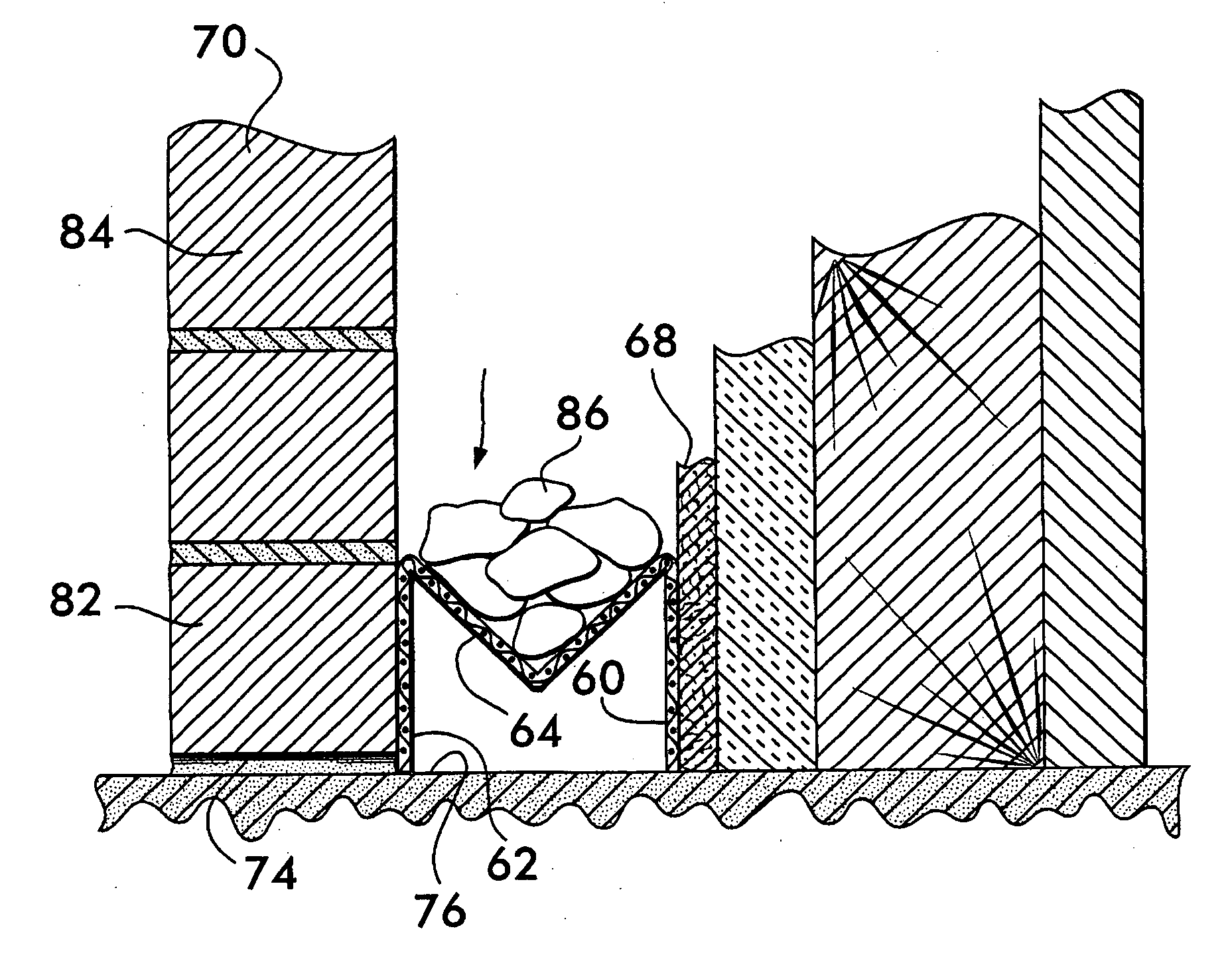
[0030]FIGS. 6-9 illustrate the present invention. The blocker 50 is provided as an elongate strip of material 52 that can be folded, bent, or flexed into an “M”shape in transverse cross section (see FIG. 7). Preferably, the material 52 has three longitudinally-extending creases, or fold lines, 54, 56 and 58, permitting the sheet of material 52 to be folded, bent or flexed into the M-shape. The legs 60 and 62 of the M-shaped blocker 50 can be engaged with the opposed wall surfaces of a wall cavity, and a central section 64 of the M-shaped blocker provides a debris collection surface, or trough, that bridges the opposed walls.

[0031] Preferably, the blocker 50 possesses a degree of resiliency such that, when flexed or folded along its creases, 54, 56 and / or 58, into a compressed M-shape, the blocker 50 exerts a force to expand outwardly in an accordion manner. For example, see the dashed lines illustrated in FIG. 7 showing the blocker in an expanded condition. In this way, when compres...


PUM


Abstract

A mortar and debris collection device for use within a cavity wall to prevent the blockage of weep holes at the base of the wall. The cavity wall assembly includes a masonry wall, an adjacent inner wall, a wall cavity therebetween, and a free-standing elongate strip of openwork material located within the cavity forming a debris collection surface a spaced distance above a base surface of the cavity. Preferably, the openwork material is inserted and positioned within the cavity after the inner wall and only a base portion of the outer masonry wall is constructed. Thereafter, the upper portion of the outer masonry wall is constructed and any mortar or debris falling into the cavity is caught and supported on the debris collection surface.

Description

CROSS-REFERENCE TO RELATED APPLICATIONS [0001] This application claims the benefit under 35 USC §119(e) of U.S. Provisional Patent Application No. 60 / 630,390, filed Nov. 23, 2004.BACKGROUND OF THE INVENTION [0002] The present invention relates to a mortar and debris collection device for use within a cavity wall to prevent the blockage of weep holes at the base of the wall, and more particularly, the present invention relates to a masonry cavity wall assembly including a mortar and debris blocker and to a method of assembling a masonry cavity wall with a mortar and debris blocker. [0003] Masonry cavity wall constructions include inner and outer vertical walls with a space or cavity existing therebetween. The inner wall can be made of a wood sheathing or like material, and the outer wall can be made of bricks, stones, blocks or the like held together by mortar. Weep holes are typically located at the base of the outer wall to permit water to drain from the cavity and to permit the ca...

Claims


Application Information

Patent Timeline
IPC IPC(8): E04B1/70
CPCE04B1/7061E04B2/707E04B2002/565
Inventor EHRMAN, GEOFFREY N.COULTON, MICHAEL S.RANDELLO, NATHAN L.
Owner BENJAMIN OBDIKE
Why Eureka
Try Eureka