
Machine for in-register mounting of flexographic printing plates

a technology machine, which is applied in the field of flexographic printing plate, can solve the problems of long acceptable time, large programming time, and the use of pointers, and achieve the effects of simple and intuitive use, convenient provision, and flexible and versatile us

Active Publication Date: 2006-06-08
BIEFFEBI SPA
View PDF15 Cites 13 Cited by
  • Summary
  • Abstract
  • Description
  • Claims
  • Application Information

AI Technical Summary

Benefits of technology

[0008] Within this aim, an object of the present invention is to provide a machine for in-register mounting of flexographic printing plates which allows to position in an optimum manner, and most of all in a single operating step, each flexographic printing plate on the corresponding printing plate cylinder, without having to perform any test print.
[0009] Another object of the present invention is to provide a machine for mounting flexographic printing plates which is extremely flexible and versatile as well as simple and intuitive to use and does not have the impression roller (however, the inventive concept can also be associated with conventional machines provided with the impression roller).
[0010] Another object of the present invention is to provide a machine which is simple, relatively easy to provide in practice, safe in use, effective in operation, and has a relatively low cost.

Problems solved by technology

It is evident that it is necessary to perform practical overlapping test prints of the image for each cylinder in order to check the achieved result of the in-register mounting of the printing plate; this of course requires considerable time for programming the positions of the printing plates and performing the test prints to check the perfect positioning of each printing plate, and such time is currently no longer acceptable, since it does not allow to achieve the optimum production rates required by the market.
The use of pointers, therefore, requires considerable time for programming, and it is possible only to check the mounting position of the references (for example, the traditional registration marks or microdots).

Method used


Image

  • Machine for in-register mounting of flexographic printing plates
  • Machine for in-register mounting of flexographic printing plates

Examples


Embodiment Construction

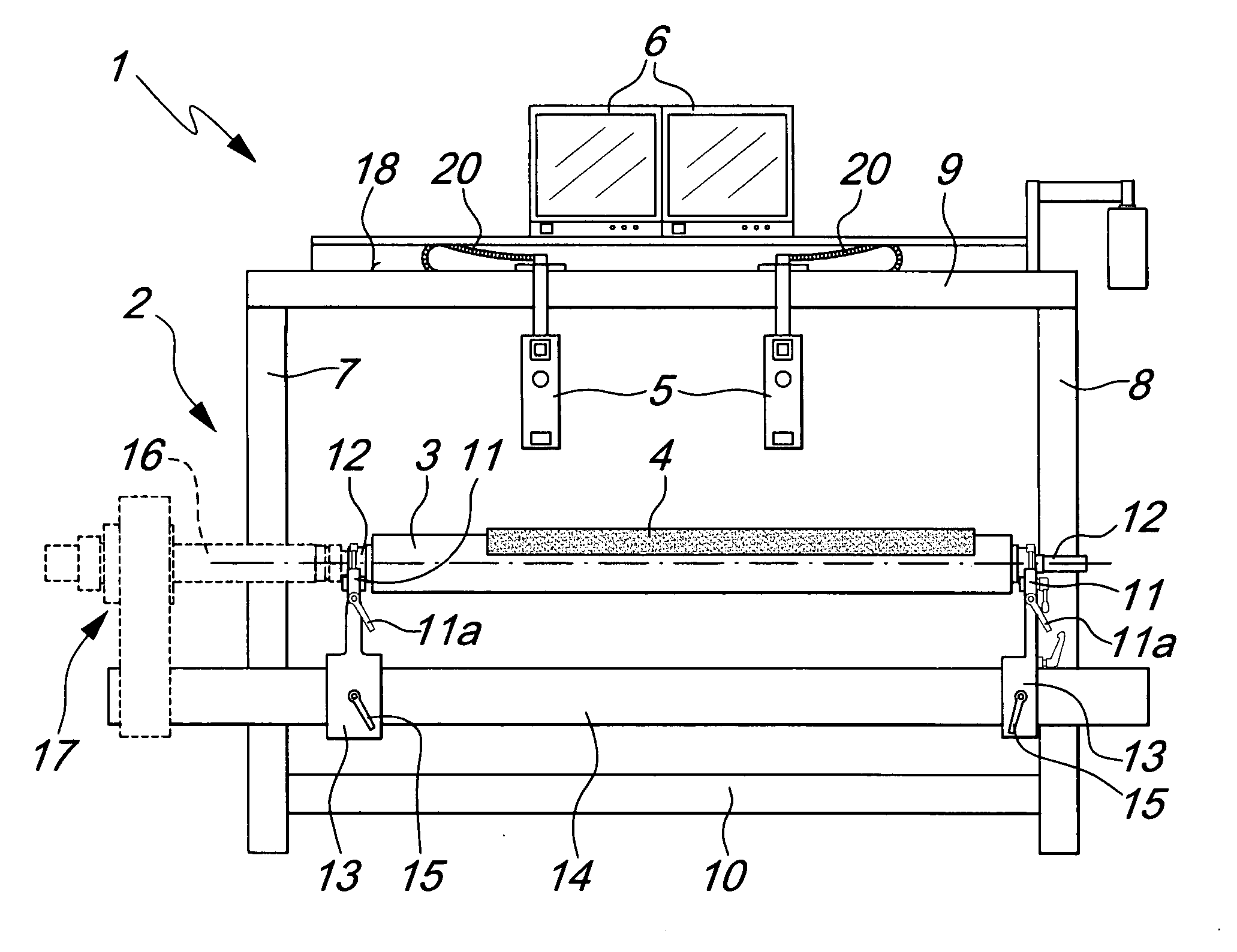
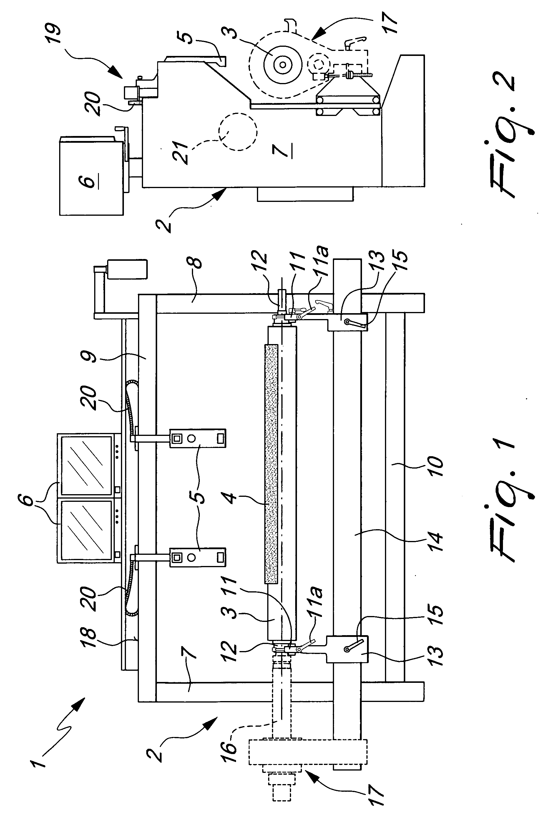
[0017] With reference to FIG. 1, the reference numeral 1 generally and schematically designates a machine for the in-register mounting of flexographic printing plates with a virtual data-processing system according to the invention, in a first embodiment thereof.

[0018] The machine comprises a footing, generally designated by the reference numeral 2, for supporting at least one printing plate cylinder 3, on which a flexographic printing plate 4 is mounted which is suitable for printing a predefined image, and at least one movable television camera 5, which is connected to a monitor 6 and is trained on the cylinder 3 and can slide parallel to the cylinder 3 in order to check the correct positioning and mounting of the printing plate.

[0019] The footing 2, of a substantially traditional type, is constituted by two vertical posts 7, 8, which are connected by beams 9, 10, and is provided at the front with crescent-shaped supports 11 for the ends 12 of the cylinder 3, said supports being...


PUM


Abstract

A machine for in-register mounting of flexographic printing plates with a virtual data-processing system, having a supporting footing for a printing plate cylinder, on which a respective flexographic printing plate is mounted, suitable for printing a predefined image, and at least one television camera, which is connected to a monitor, is trained onto the cylinder and can slide parallel to the cylinder to check correct positioning-mounting of the printing plate, the television camera being associated with position sensors and connected to a device for the real-time processing and display of at least one composite image, for allowing the operator to perform precise position comparisons for optimum plate mounting between a preprocessed graphical reproduction of the image to be printed, provided on a digital memory composed of graphical memory associated with position measurements, and the position of the printing plate.

Description

[0001] The present invention relates to a machine for in-register mounting of flexographic printing plates with a virtual data-processing system. BACKGROUND OF THE INVENTION [0002] Currently, flexographic printing plates for printing machines are generally mounted on the printing plate cylinder by aligning as precisely as possible reference points (for example the traditional registration marks) provided on the printing plates with respective reference markings (often still marked by hand) on the sheets of paper on which the test prints are to be performed. [0003] Modern machines avoid having to perform this alignment of reference markings every time with the naked eye, since optical magnification means are provided or, in the most advanced versions, television cameras are provided which allow to view under magnification the chosen points to be aligned. [0004] Once the fixing of a first printing plate related to one color has been performed correctly and once the test print with sai...

Claims


Application Information

Patent Timeline
IPC IPC(8): B41F33/00B41F5/20B41F5/00B41F15/00
CPCB41F27/005B41F27/00B41F27/12
Inventor ZANOLI, ALBERTOSAMBRI, STEFANO
Owner BIEFFEBI SPA
Learn More