Cooling device

Active Publication Date: 2006-06-08
PANASONIC CORP
View PDF10 Cites 5 Cited by
  • Summary
  • Abstract
  • Description
  • Claims
  • Application Information

AI Technical Summary

Benefits of technology

[0015] According to the cooling device of the present invention, the cooling efficiency can be improved by the centrifugal pump in the casing,

Problems solved by technology

However, since the registered design evidently has no relation to a pump for a cooling device, the above registered design cannot be applied to a pump for a cooling device (see Japanese Registered Design Publication No. 775382).
Also, since the heat exchange basically depends on the material of the refrigerant, heat can be exchanged within a certain extent, and thus the cooling efficiency cannot be further improved.
In addition, since the structure of the liquid driving mechanism becomes complex, and the flow rate of the refrigerant becomes small in a reciprocating pump and the like

Method used


Image

  • Cooling device
  • Cooling device
  • Cooling device

Examples


first embodiment

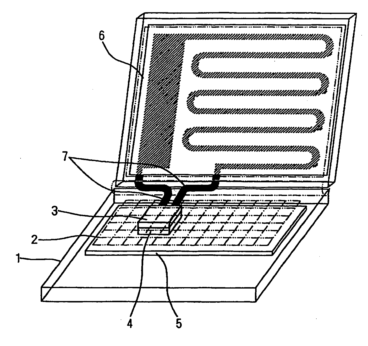
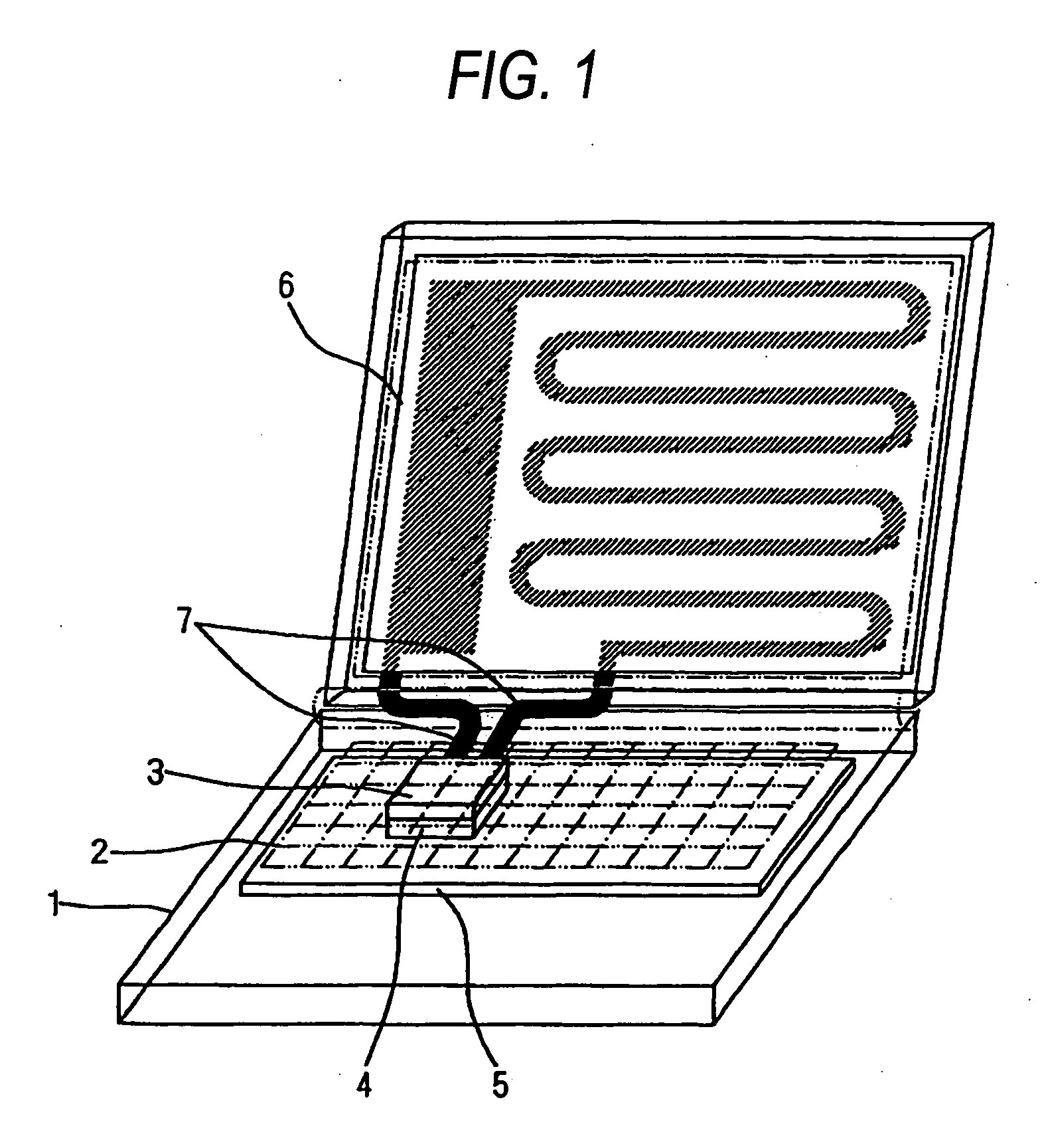
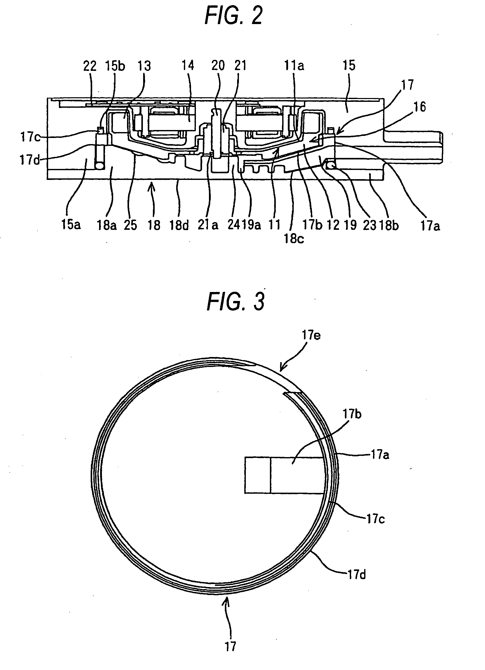
[0038] A centrifugal pump of a cooling device according to a first embodiment of the present invention will be described. The centrifugal pump of the first embodiment has a recessed conical surface formed in a heat-receiving casing. FIG. 1 is a perspective view of an electronic apparatus in which the cooling device of the first embodiment according to the present invention is provided, FIG. 2 is a cross-sectional view of the centrifugal pump of the cooling device according to the first embodiment of the present invention, FIG. 3 is a front view of a ring-shaped sealing member of the centrifugal pump according to the first embodiment of the present invention, FIG. 4 is a front view of a lower casing of the centrifugal pump according to the first embodiment of the present invention, FIG. 5 is a cross-sectional view of the lower casing taken along the line V-V in FIG. 4, FIGS. 9A and 9B are perspective views illustrating the outer shape of the centrifugal pump according to the first em...

second embodiment

[0059] A centrifugal pump according to a second embodiment of the present invention will be described. In the centrifugal pump of the second embodiment, the center portion of the recessed portion of a heat-receiving casing is formed with tiny steps. FIG. 6 is a front view of a lower casing of the centrifugal pump according to the second embodiment of the present invention, and FIG. 7 is a cross-sectional view of the lower casing taken along the line VII-VII in FIG. 6. Since the centrifugal pump of the second embodiment has basically the same structure as that of the first embodiment, FIGS. 1 to 3 will be referred. Members having the same reference numeral as those of the first embodiment have basically the same function and property as those in the first embodiment, and the detailed description thereof s will be omitted herein.

[0060] In FIGS. 6 and 7, a reference numeral 26 represents a stepped portion that is formed in a recessed conical surface of a conical thick portion 18a. A p...


PUM


Abstract

A cooling device including a heat-radiating device and a centrifugal pump provided in a closed circulation passage for circulating refrigerant. The centrifugal pump comes into contact with heat-generating electronic parts to absorb heat from the heat-generating electronic parts by the heat exchange of the refrigerant therein to radiate the heat via the heat-radiating device. A pump chamber of the centrifugal pump is defined by a combination of a plurality of casings, that is, an upper casing, a ring-shaped sealing member and a lower casing. A contacting surface that comes in a surface contact with the heat-generating electronic parts, and a recessed conical surface that faces an impeller are formed in the lower casing of the casings that comes into a direct contact with the heat-generating electronic parts. A plurality of heat-radiating pins protruding toward the impeller is provided in a center portion of the recessed conical surface.

Description

[0001] This application is based on Japanese Patent Application No. 2004-142032, which is incorporated herein by reference. BACKGROUND OF THE INVENTION [0002] 1. Field of the Invention [0003] The present invention relates to a cooling device for electronic parts, which cools heat-generating electronic parts such as a microprocessor (hereinafter referred to as a CPU) installed in a housing by the circulation of refrigerant. [0004] 2. Description of the Related Art [0005] In recent years, computer speed increases rapidly, and thus the clock frequency of the CPU becomes extremely large as compared to that of the old days. As a result, the amount of heat generated by the CPU increases considerably, and thus the computer cannot be cooled sufficiently only by the air cooling of a heat sink, and it is indispensable to install a high-efficiency and high-output cooling device. As a result, a cooling device that circulates refrigerant to cool a board on which heat-generating electronic parts ...

Claims


Application Information

Patent Timeline
IPC IPC(8): H05K7/20F25D17/02F04D29/58F25D9/00G06F1/20H01L23/473
CPCF04D29/588G06F1/203G06F2200/203H01L23/473H01L2924/0002H01L2924/00
Inventor KOGA, SHINYAGOTO, NOBUYUKIANAMI, TETSUYAMATSUDA, TOSHIHIKO
Owner PANASONIC CORP
Why Eureka
Try Eureka