Sound arresting barrier

a sound barrier and arresting technology, applied in the field of acoustic structures, can solve the problem that the sound barrier of the past has only offered minimal protection

Inactive Publication Date: 2006-06-08
M H CORBIN
View PDF12 Cites 13 Cited by
  • Summary
  • Abstract
  • Description
  • Claims
  • Application Information

AI Technical Summary

Benefits of technology

[0004] The present invention provides a sound barrier system that not only reduces noise transmitted from roadways, railways or other noise generating areas, but also serves as an impact barrier for errant vehicles which may strike the barrier. In one embodiment, the sound barrier comprises a series of spaced vertical posts, or support members, arranged in a desired area between the noise source and the area to be protected, such as along a roadway, railway, or other noise generating area. A plurality of elongate sound arresting members extend generally between the support members and are stacked one atop another to form a barrier wall. Each sound arresting member is connected at its distal ends to the vertical support members by elongate transition connectors coupled to each support member and spaced apart along the lengths of the support members. Each transition connector has an arm extending toward an oppositely disposed one of the support members. The arms are received in apertures formed in the ends of the sound arresting members such that the sound arresting members are frictionally engaged by the transition connectors.

Problems solved by technology

Previous sound barriers have offered only minimal protection against the passage of vehicles through the structure.

Method used


Image

  • Sound arresting barrier
  • Sound arresting barrier
  • Sound arresting barrier

Examples


Embodiment Construction

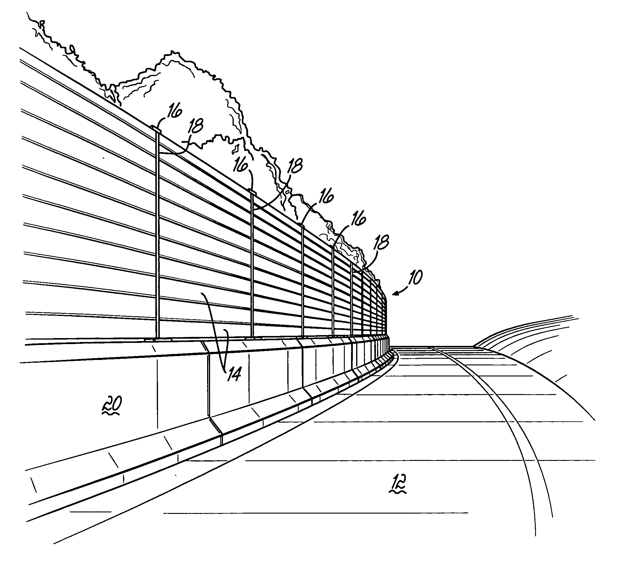
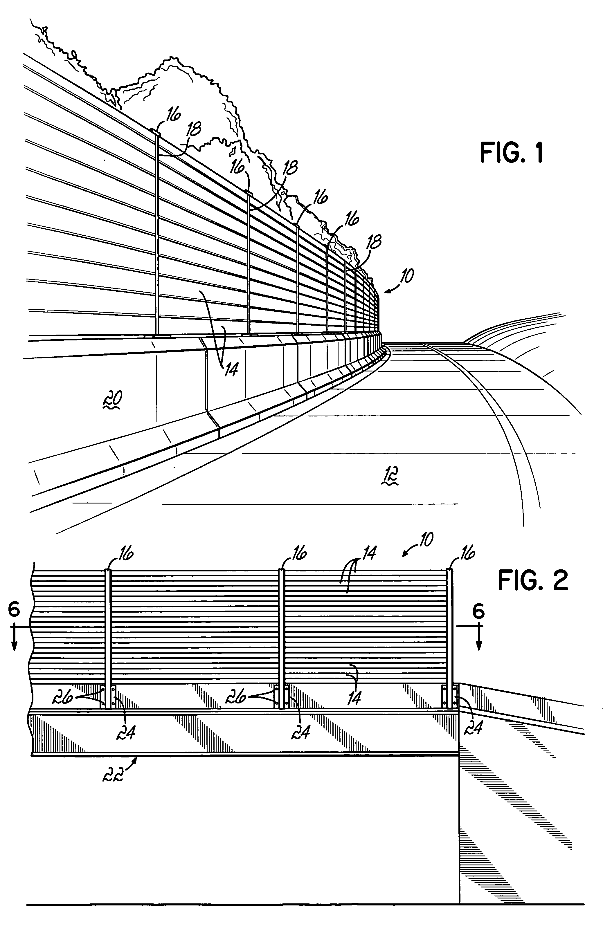
[0018]FIG. 1 depicts an exemplary sound barrier 10 according to the present invention and utilized along a roadway 12 to eliminate or reduce noise transmitted from the roadway 12 to the adjacent area on the opposite side of the sound barrier 10. The sound barrier 10 comprises a series of elongate sound arresting members 14 arranged end-to-end and stacked in a vertical direction, one atop another, to create a wall or partition between the noise generating area and the area to be protected. The sound arresting members 14 are supported by a series of spaced vertically disposed posts, or support members 16, arranged along the boundary between the noise source and the protected area. Vertical cover strips 18 are provided along the joints between the ends of the sound arresting members 14, generally opposite the support members 16. In FIG. 1, the sound barrier 10 is constructed along the side of the roadway 12 and is positioned atop a parapet or retaining wall 20. It will be recognized ho...


PUM


Abstract

A sound barrier comprises a plurality of elongate sound arresting members arranged end to end and stacked vertically, one upon another, to form a barrier wall. The sound arresting members are disposed generally between a plurality of spaced vertical support members and are secured thereto by a plurality of elongate transition connectors coupled to each support members. The elongate transition connectors have distal ends that extend in directions toward oppositely disposed support members and are received within apertures formed in respective ends of the sound arresting members at their respective ends.

Description

FIELD OF THE INVENTION [0001] The present invention relates generally to acoustic structures, and more particularly to a sound barrier for eliminating or reducing noise emanating from roadways, railways, airports or other noise generating areas.BACKGROUND OF THE INVENTION [0002] Sound barrier walls are known in the art and have been utilized to reduce or eliminate noise transmitted from roadways, airports, railways, or other such areas to adjacent residential and business communities. These sound barriers are typically constructed in the form of elongate wall structures interposed between the noise source and the area that is desired to be protected from the noise. When such sound barriers are erected along roadways and bridges, it is desirable to construct the sound barrier such that it is able to act as an impact barrier structure as well as a noise barrier. In particular, it is desirable to prevent automobiles, trucks and other vehicles from passing through the barrier into the a...

Claims


Application Information

Patent Timeline
Patent Type & Authority Applications(United States)
IPC IPC(8): B64F1/26E04H17/00G10K11/00E04B1/00E04B9/00
CPCB64F1/26E01F8/0011E01F8/007G10K11/16
Inventor CORBIN, MAXWELL H. JR.BURCH, LEE
Owner M H CORBIN
Why Eureka
Try Eureka