
Arrangement for vibration damping in a steering column

a technology for steering columns and steering columns, which is applied in the direction of shock absorbers, mechanical equipment, transportation and packaging, etc., can solve the problems of increasing the number of seals subject to vibration, and reducing the service life of rubber bushings. , to achieve the effect of simple and maintenance-fr

Inactive Publication Date: 2006-06-08
VOLVO LASTVAGNAR AB
View PDF23 Cites 10 Cited by
  • Summary
  • Abstract
  • Description
  • Claims
  • Application Information

AI Technical Summary

Benefits of technology

[0007] An object of the invention is therefore to provide an arrangement for bringing about a simple, maintenance-free vibration damper, which can also be adapted to different frequencies if required.

Problems solved by technology

The disadvantage of this type of damper is that a rubber bushing loses its elasticity as it ages and dries out, with crack formation and an impaired damping function as a consequence.
The disadvantage of this solution is that it comprises a number of seals which are subjected to vibrations from the wheels and the steering linkage and also to radial loads when rotation and turning of the steering column take place.
There is therefore a constant risk of leakage of damping liquid, which in turn would lead to extensive fault-tracing and complicated repair.

Method used


Image

  • Arrangement for vibration damping in a steering column
  • Arrangement for vibration damping in a steering column
  • Arrangement for vibration damping in a steering column

Examples


Embodiment Construction

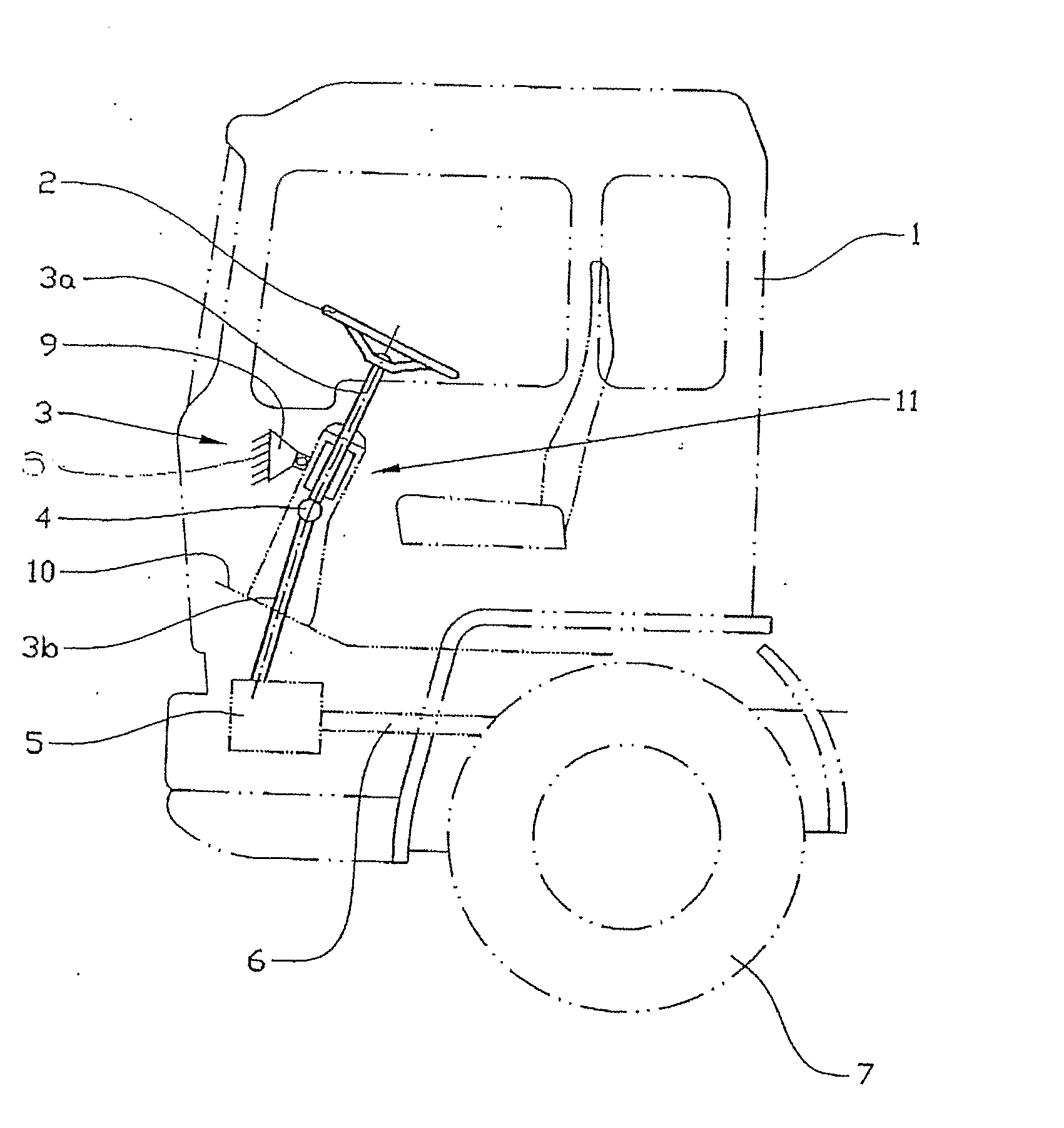
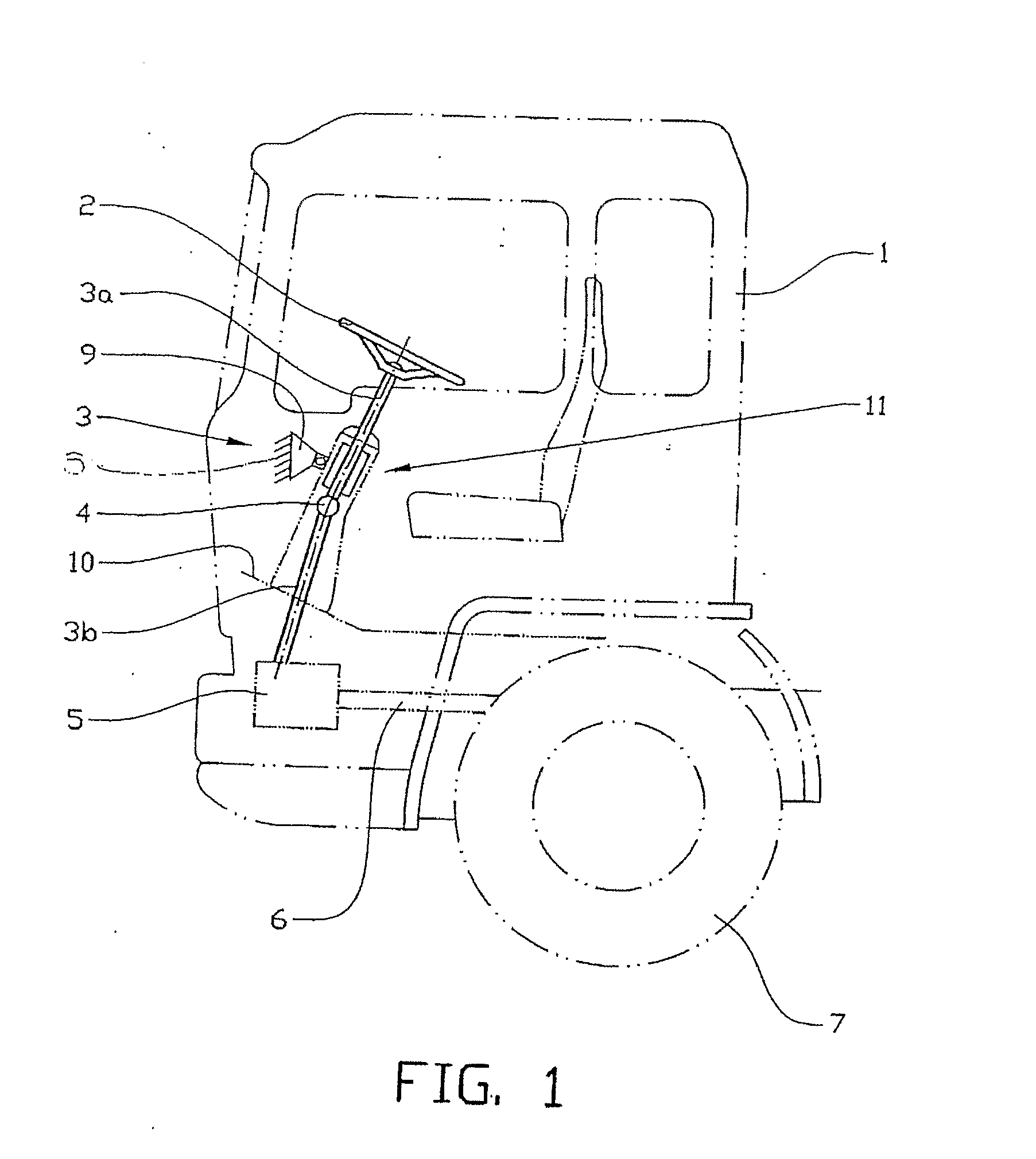
[0019]FIG. 1 shows diagrammatically a vehicle with a cab 1 in which a steering wheel 2 for steering the vehicle is mounted. The steering wheel 2 is connected to a steering main shaft 3 which can comprise (including, but not necessarily limited to) one or more portion(s) 3a, 3b preferably connected to one or more universal joints 4. The steering main shaft 3 is connected to a steering gear 5 which, via a steering linkage 6, can act on a pair of wheels 7 in order to steer the vehicle. The steering main shaft can extend in a support 8, the upper part of which is provided with an attachment 9 mounted on the cab or dashboard of the vehicle, and the lower part of which is fixed to the floor 10 of the cab.

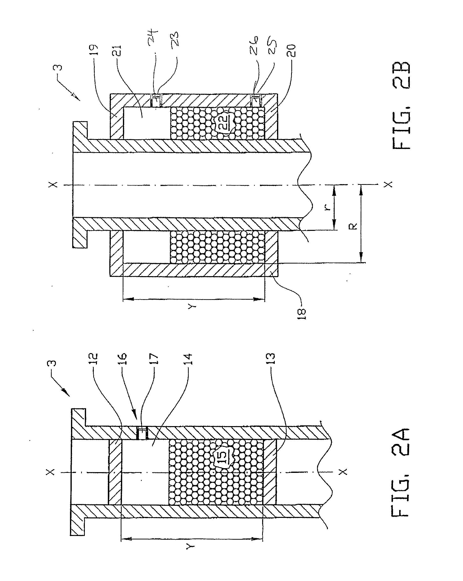
[0020] The upper part 3a of the steering main shaft 3 is provided with a vibration damper 11, which can be located in or around the steering main shaft, as can be seen from FIGS. 2A-D.

[0021]FIG. 2A shows a steering main shaft 3 with a circular cross section and with a cylindrical basic ...


PUM


Abstract

Method and arrangement for damping vibrations in a vehicle steering wheel mounted on a steering main shaft connected to a pair of steered wheels via a steering linkage. According to a preferred embodiment, the steering main shaft comprises an inner or outer hollow portion along its longitudinal axis, which portion is filled with a granular material to a predetermined level. This level is proportional to the shape and cross-sectional area of the hollow portion and also the frequency range of the vibrations to be damped. By measuring the dimensions of the hollow portion, the volume of a predetermined material with a given density which is required in order to damp vibrations in a frequency range applying for the vehicle can be calculated.

Description

CROSS-REFERENCE TO RELATED APPLICATION [0001] The present application is a continuation patent application of International Application No. PCT / SE2004 / 000266 filed 27 Feb. 2004 which was published in English pursuant to Article 21(2) of the Patent Cooperation Treaty, and which claims priority to Swedish Application No. 0301 060-0 filed 10 Apr. 2003. Said applications are expressly incorporated herein by reference in their entireties.TECHNICAL FIELD OF THE INVENTION [0002] The invention relates to an arrangement for damping vibrations in a vehicle steering wheel mounted on a steering main shaft connected to a pair of steered wheels via a steering linkage. BACKGROUND OF THE INVENTION [0003] One type of vibration damper is previously known from GB 2 274 263, which describes a damping rubber bushing in the steering linkage for damping vibrations from the roadway and imbalance in the steered wheels of the vehicle. The disadvantage of this type of damper is that a rubber bushing loses its...

Claims


Application Information

Patent Timeline
Patent Type & Authority Applications(United States)
IPC IPC(8): B62D7/22B62D1/16
CPCY10T464/50B62D7/224F16F15/363F16F7/015F16F15/10
Inventor BODIN, JAN-OLOF
Owner VOLVO LASTVAGNAR AB
Learn More