Gas turbine combustion chamber

a combustion chamber and gas turbine technology, applied in the direction of machines/engines, burner noise reduction, lighting and heating apparatus, etc., can solve the problems of increased vibration, heat release fluctuation, thermoacoustic oscillation of this type in the combustion chamber, etc., and achieve the effect of simple and heat-resistan

Inactive Publication Date: 2012-09-20
SIEMENS AG
View PDF13 Cites 1 Cited by
  • Summary
  • Abstract
  • Description
  • Claims
  • Application Information

AI Technical Summary

Benefits of technology

[0012]In an advantageous embodiment the corrugated component has at least two corrugation troughs. The corrugated component is welded or soldered to the combustion chamber wall in said corrugation troughs. This ensures in a simple manner that the resonance chambers are kept separated even during thermal expansion of the corrugated component and / or thermal expansion of the combustion chamber wall. In addition this represents a simple, heat-resistant way of fixing the corrugated component to the combustion chamber wall.
[0013]At least two separate resonance chambers advantageously have different volumes. This likewise enables different frequencies to be attenuated.

Problems solved by technology

However, variations in fuel quality and sundry other thermal or acoustic perturbations lead to fluctuations in the quantity of heat released.
At the same time an interaction takes place between acoustic and thermal perturbations which can produce increased vibrations.
Thermoacoustic oscillations of this type in the combustion chambers of gas turbines—or indeed turbo machines in general—pose a problem in relation to the design and operation of new combustion chambers, combustion chamber components and burners for turbo machines of said type.
An intensifying interaction between thermal and acoustic perturbations can build up in the process which can cause the combustion chamber to be subjected to heavy stresses and lead to increasing emissions.
However, this is very time-consuming, labor-intensive and expensive.
Furthermore, these small boxes and their welded seam have only a very limited lifespan.

Method used


Image

  • Gas turbine combustion chamber
  • Gas turbine combustion chamber

Examples


Embodiment Construction

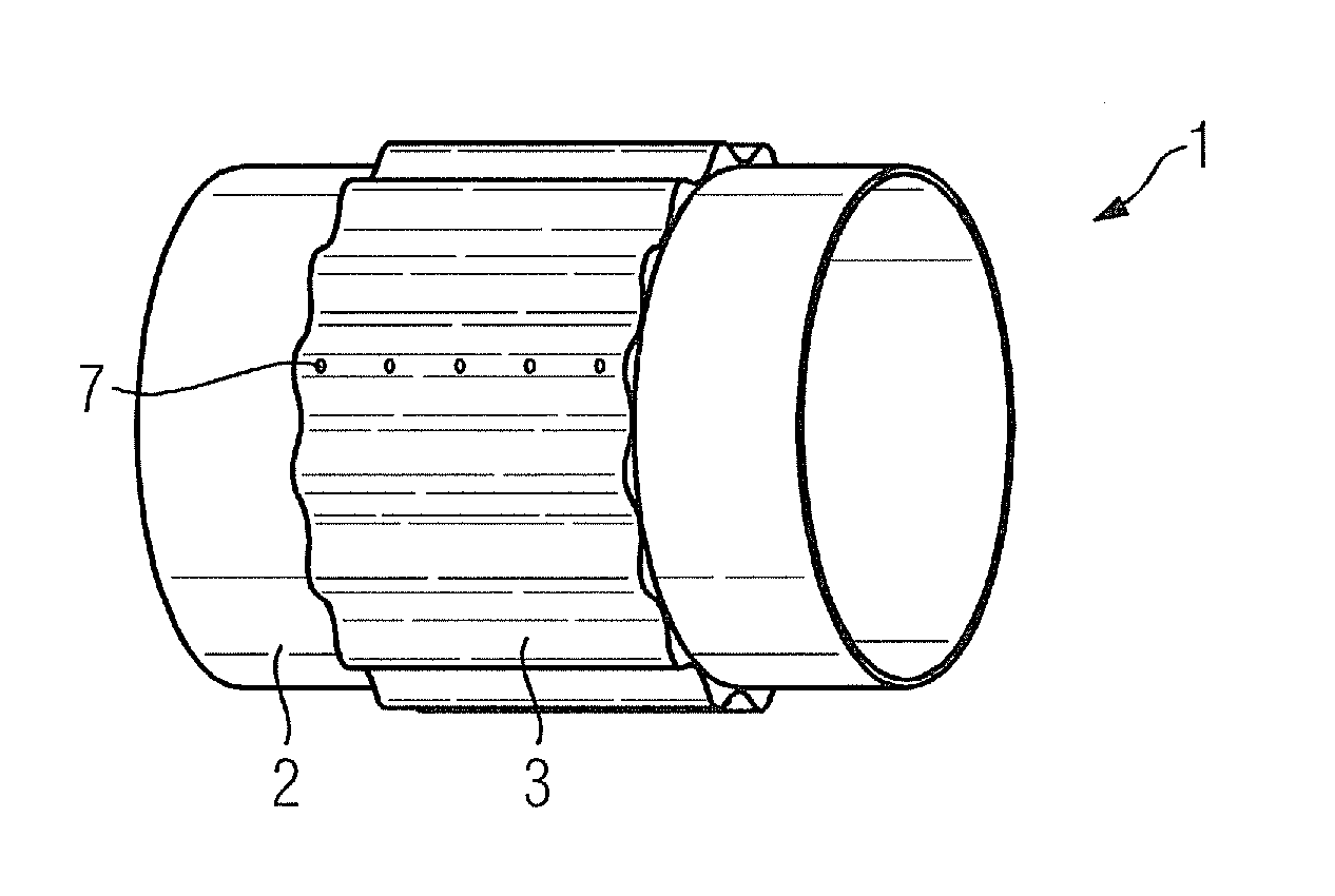
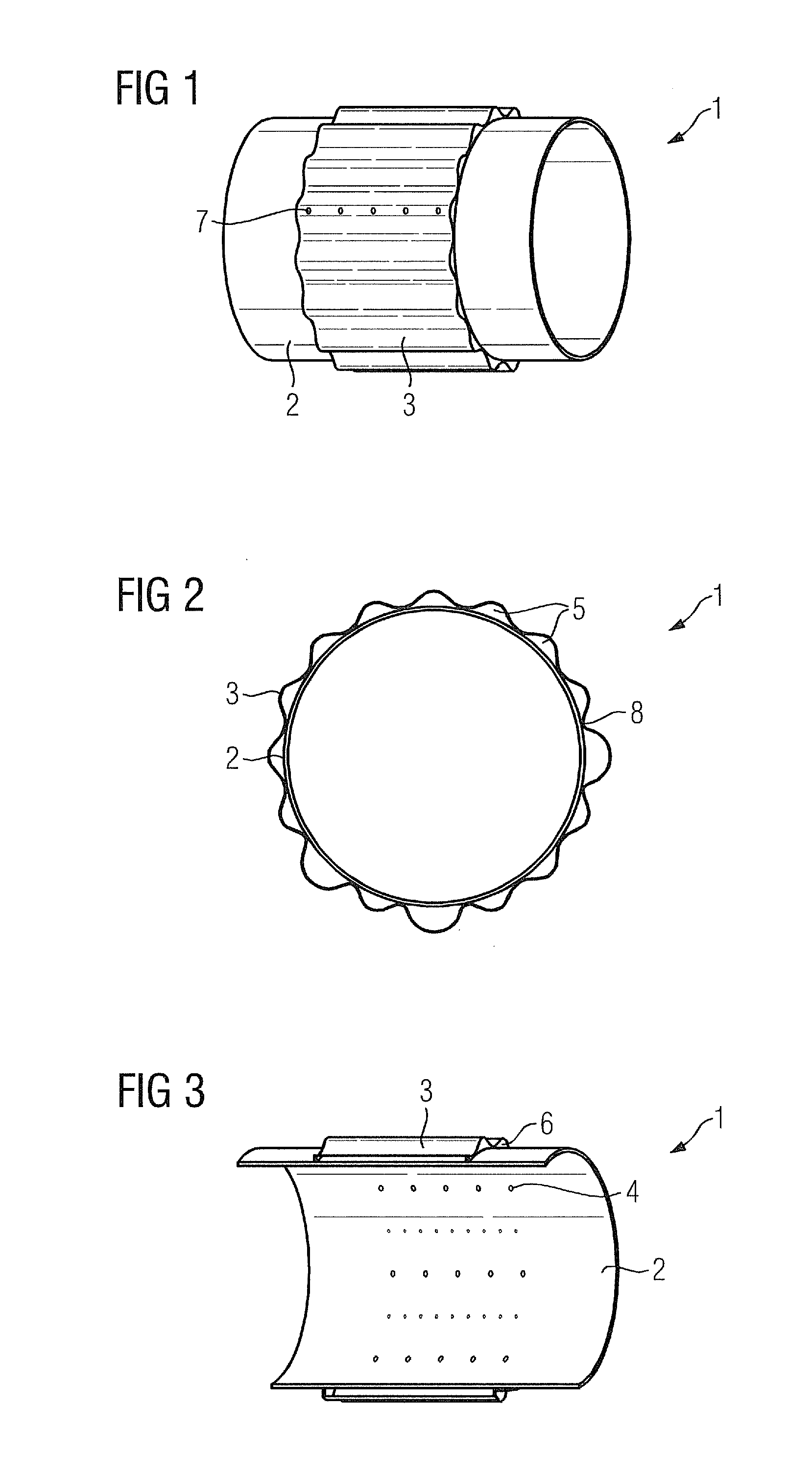
[0018]FIG. 1 shows a sectional view of an inventive gas turbine combustion chamber 1. The gas turbine combustion chamber 1 additionally has a combustion chamber interior and a combustion chamber wall 2 with a substantially rotationally symmetrical cross-section. A corrugated component 3 is arranged over the entire circumference of the combustion chamber wall 2 on the side of the combustion chamber wall 2 facing away from the combustion chamber interior. In this case the corrugated component 3 can be a metal plate. In combination with the combustion chamber wall 2 (FIG. 2), the component 3 embodies a plurality of separate resonance chambers 5. Openings 4 (FIG. 3) are incorporated in the combustion chamber wall 2 in such a way that a fluidic connection is established in each case between the combustion chamber interior and one of the resonance chambers 5 (FIG. 2). At least one opening 4 (FIG. 3) is therefore associated with each resonance chamber 5 (FIG. 2). The corrugated component 3...


PUM


Abstract

A gas turbine combustion chamber is provided. The gas turbine includes a combustion chamber interior and a combustion chamber wall which has a substantially rotationally symmetrical cross-section, wherein on the side of the combustion chamber wall facing away from the combustion chamber interior there is arranged over the entire cross-sectional circumference of the combustion chamber wall a corrugated component which, in combination with the combustion chamber wall, embodies a plurality of separate resonance chambers and wherein openings are incorporated in the combustion chamber wall in such a way that a fluidic connection is established in each case between the combustion chamber interior and one of the resonance chambers and wherein the corrugated component has two locking rings which are connected to the combustion chamber wall in order to seal off the resonance chambers.

Description

CROSS REFERENCE TO RELATED APPLICATIONS[0001]This application claims priority of European Patent Office application No. 11158268.0 EP filed Mar. 15, 2011. All of the applications are incorporated by reference herein in their entirety.FIELD OF INVENTION[0002]The invention relates to a gas turbine combustion chamber, comprising a combustion chamber interior and a combustion chamber wall which has a substantially rotationally symmetrical cross-section.BACKGROUND OF INVENTION[0003]In the simplest case a gas turbine plant comprises a compressor, a combustion chamber and a turbine. Ingested air is compressed in the compressor and a fuel is then mixed therewith. The mixture is combusted in the combustion chamber, the exhaust gases from the combustion process being supplied to the turbine, by which energy is extracted from the combustion exhaust gases and converted into mechanical energy.[0004]However, variations in fuel quality and sundry other thermal or acoustic perturbations lead to flu...

Claims


Application Information

Patent Timeline
Patent Type & Authority Applications(United States)
IPC IPC(8): F02C7/24
CPCF23D2210/00F23M20/005F23R2900/00014F23R3/00F23M99/005
Inventor BOTTCHER, ANDREASDEISS, OLGA
Owner SIEMENS AG
Why Eureka
Try Eureka