Method for turning a radio filter, a radio filter and a system comprising such a radio filter

a radio filter and filter technology, applied in the direction of resonant circuit details, line-transmission details, resonant circuits using central processing units, etc., can solve the problems of filter not having the possibility to adjust itself, no longer being able to find one-to-one correspondence, built-in fault, etc., to achieve the effect of reducing the cost of manufacturing radio filters for different operating frequencies, and reducing the cost of filtering

Inactive Publication Date: 2005-07-14
INTEL CORP
View PDF9 Cites 2 Cited by
  • Summary
  • Abstract
  • Description
  • Claims
  • Application Information

AI Technical Summary

Benefits of technology

[0010] An advantage with the present invention is that the cost for manufacturing radio filters for different operating frequencies, and systems comprising a filter, is reduced since one filter can be used for said different operating frequencies.
[0011] Another advantage with the present invention is that the method allows radio filters to be easily tuned, for a specific frequency, in the field, as a response to the input signal(s).
[0012] Still another advantage is that the radio filter easily may be tuned to another frequency during operation.
[0013] Still another advantage is that the method provides a radio filter to be, during normal operation, adjusted in response to external influence, such as temperature drifts, aging, air humidity, external force.

Problems solved by technology

The problem with the described control system is that it requires a one-to-one correspondence between the position of the tuning mechanism in a certain resonator module and the measured phase.
When resonator modules are coupled in cascade, this one-to-one correspondence is no longer possible to find.
The described filter has a built-in fault in that the filter doesn't have any possibilities to adjust it self over time, for instance to compensate for temperature drifts.

Method used


Image

  • Method for turning a radio filter, a radio filter and a system comprising such a radio filter
  • Method for turning a radio filter, a radio filter and a system comprising such a radio filter
  • Method for turning a radio filter, a radio filter and a system comprising such a radio filter

Examples


first embodiment

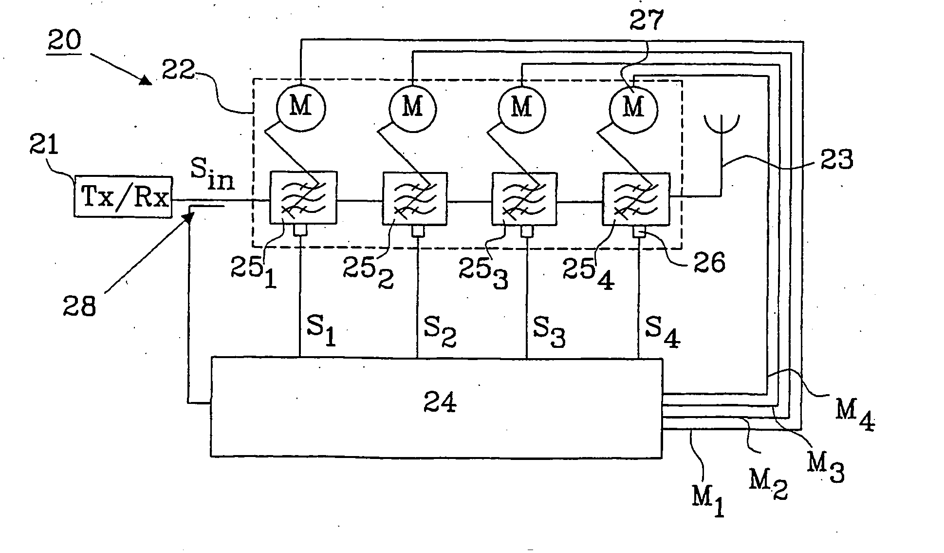
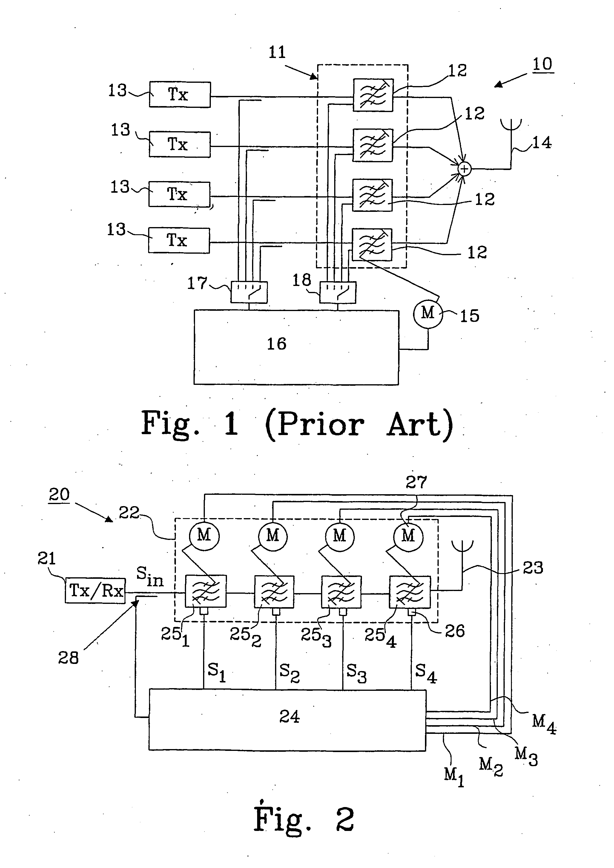
[0035]FIG. 2 shows a system 20 comprising a transceiver circuit 21 connected to a radio filter 22 according to the invention, an antenna 23 connected to an output from the radio filter 22 and a control unit 24. The filter comprises at least two resonator modules 25 coupled in cascade, in this embodiment there is four resonator modules 251-254 coupled in cascade. Each resonator module 25 being provided with a probe 26 and a tuning mechanism 27.

[0036] A sensor 28 is connected to the control unit 24, which detects if there is any signal Sin coming from the transceiver circuit 21 and furthermore senses the frequency content of signal Sin.

[0037] The frequency content is used in the control unit to determine the filter frequency, i.e. around which frequency the filter should operate, and as a reference to the measured signals from the probes.

[0038] Each probe 26 is used for measuring a signal parameter, e.g. phase or amplitude, at the resonator module, and is connected to the control un...

second embodiment

[0103]FIG. 9 shows a radio filter 93 according to the invention comprising an isolator circuit 94, provided between a transmitter circuit (not shown) and the input connection 95 to a first resonator module 961. The first resonator module 961 is cascade coupled with a second resonator module 962 and a third resonator module 963. An additional fourth resonator module 964 is parallel coupled with the second resonator module 962 and all present resonator modules are provided with tuning mechanisms (not shown) and probes 26 to measure signal parameters within each resonator module. The third resonator module is connected to an output connection 97.

[0104] A control unit 24 is provided, which receive information from the resonator modules from the probes 26 and a sensor 28 at the input connection 95 measures a reference signal Sref, as previously described in connection with FIG. 2.

[0105] The control unit 24 is also connected to the isolation circuit 94. A detection signal Sdet, which is ...

third embodiment

[0107]FIG. 10 shows a radio filter 100 according to the invention. Only the probes 26., the resonator modules 1011-1014 and the control unit 24 are illustrated. The output of the first resonator module 1011 and the input to the final resonator 1014 are directly connected by a connection 102. The control unit receive information regarding frequency content of the input signal S1, which may be done by a sensor, an isolator circuit or as an external signal as illustrated in FIG. 12. A reference signal is not measured in this example. Instead a self generated reference, within the control unit, is used as a reference when measuring the signal parameters at the resonator modules 1011-1014. Control signals M1-M4 are used to tune the filter.


PUM


Abstract

The present invention relates to a method for tuning a radio filter. The filter comprises an input connection, an output connection and at least two resonator modules coupled in cascade, each having a tuning mechanism and a probe. A first resonator module is connected to the input connection and a final resonator module is connected to the output connection. The filter is adapted to receive at least one signal within a frequency range. The method comprises essentially two steps: coarse tuning, which is dependent on the frequency content of the received signal(s), and fine tuning, which is dependent on a calculated deviation between a set value vector and a measured signal parameter vector. A relationship between the set value vector and the signal parameter vector is established for calculating the deviation. The invention also relates to a radio filter and a system comprising such a radio filter.

Description

TECHNICAL FIELD [0001] The present invention relates to a method for tuning a radio filter, especially a radio filter comprising cascade coupled resonator modules. The invention also relates to a radio filter and a system comprising such a radio filter. BACKGROUND AND RELATED ART OF THE INVENTION [0002] The control system in present auto tuned combiners works independently for each resonator module (channel), the phase is measured in each resonator module and the position of the tuning mechanism is adjusted accordingly. In U.S. Pat. No. 6,041,083, by Larsson et al., the processing is done in one control unit, switching between channels, but the measured data and response is for one channel at a time, see FIG. 1. [0003] The problem with the described control system is that it requires a one-to-one correspondence between the position of the tuning mechanism in a certain resonator module and the measured phase. When resonator modules are coupled in cascade, this one-to-one corresponden...

Claims


Application Information

Patent Timeline
Patent Type & Authority Applications(United States)
IPC IPC(8): H03J1/00
CPCH03J1/0008
Inventor MATTSSON, THOMASJANSSON, ANDERS
Owner INTEL CORP
Why Eureka
Try Eureka