
Battery pack with built in communication port

a technology of battery pack and communication port, which is applied in the field of battery pack assembly, can solve the problems of increasing the assembly and fabrication cost increasing the contamination of the electronic unit, so as to increase the reliability of communication with the host unit

Inactive Publication Date: 2006-06-08
SYMBOL TECH LLC
View PDF15 Cites 18 Cited by
  • Summary
  • Abstract
  • Description
  • Claims
  • Application Information

AI Technical Summary

Benefits of technology

This solution reduces fabrication costs, enhances reliability by replacing worn-out contacts with new ones each time the battery pack is changed, and provides effective protection against contamination, vibration, and shock, while maintaining communication and power transfer functionality.

Problems solved by technology

In particular, many electronic units, such as; hand hold mobile terminals, communication units, and the like have various assembly costs and are generally susceptible to damage during employment in harsh environments.
Typically, such dedicated communication ports increase assembly and fabrication costs of the electronic unit.
Moreover, openings that are associated with such interface components generally cause a contamination of the electronic unit, e.g. moisture and other fine particles can enter the unit and affect its performance during lifetime of the unit.
The reliability of the dedicated communication ports can also be affected over time.
Nonetheless, such gasket arrangements require regular inspection and maintenance to assure proper functionality in harsh environments, e.g. high humidity and temperature, presence of corrosive agents and the like.
Such mechanical shocks typically affect the reliability of the connection for the communication points.
At the same time, such electronic units typically include various replaceable battery arrangements having electrical / mechanical contacts that are subject to wear and tear during a lifetime of the electronic unit.
Such conducting members are typically subject to wear and tear, which in a life time of the electronic unit can affect its performance.

Method used


Image

  • Battery pack with built in communication port
  • Battery pack with built in communication port
  • Battery pack with built in communication port

Examples


Embodiment Construction

[0024] The present invention is now described with reference to the drawings, wherein like reference numerals are used to refer to like elements throughout. In the following description, for purposes of explanation, numerous specific details are set forth in order to provide a thorough understanding of the present invention. It may be evident, however, that the present invention may be practiced without these specific details. In other instances, well-known structures and devices are shown in block diagram form in order to facilitate describing the present invention.

[0025] As used in this application, the term “computer component” is intended to refer to a computer-related entity, either hardware, a combination of hardware and software, software, or software in execution. For example, a computer component may be, but is not limited to being, a process running on a processor, a processor, an object, an executable, a thread of execution, a program, and / or a computer. By way of illust...


PUM

PropertyMeasurementUnit
surface areasaaaaaaaaaa
sizeaaaaaaaaaa
humidityaaaaaaaaaa

Abstract

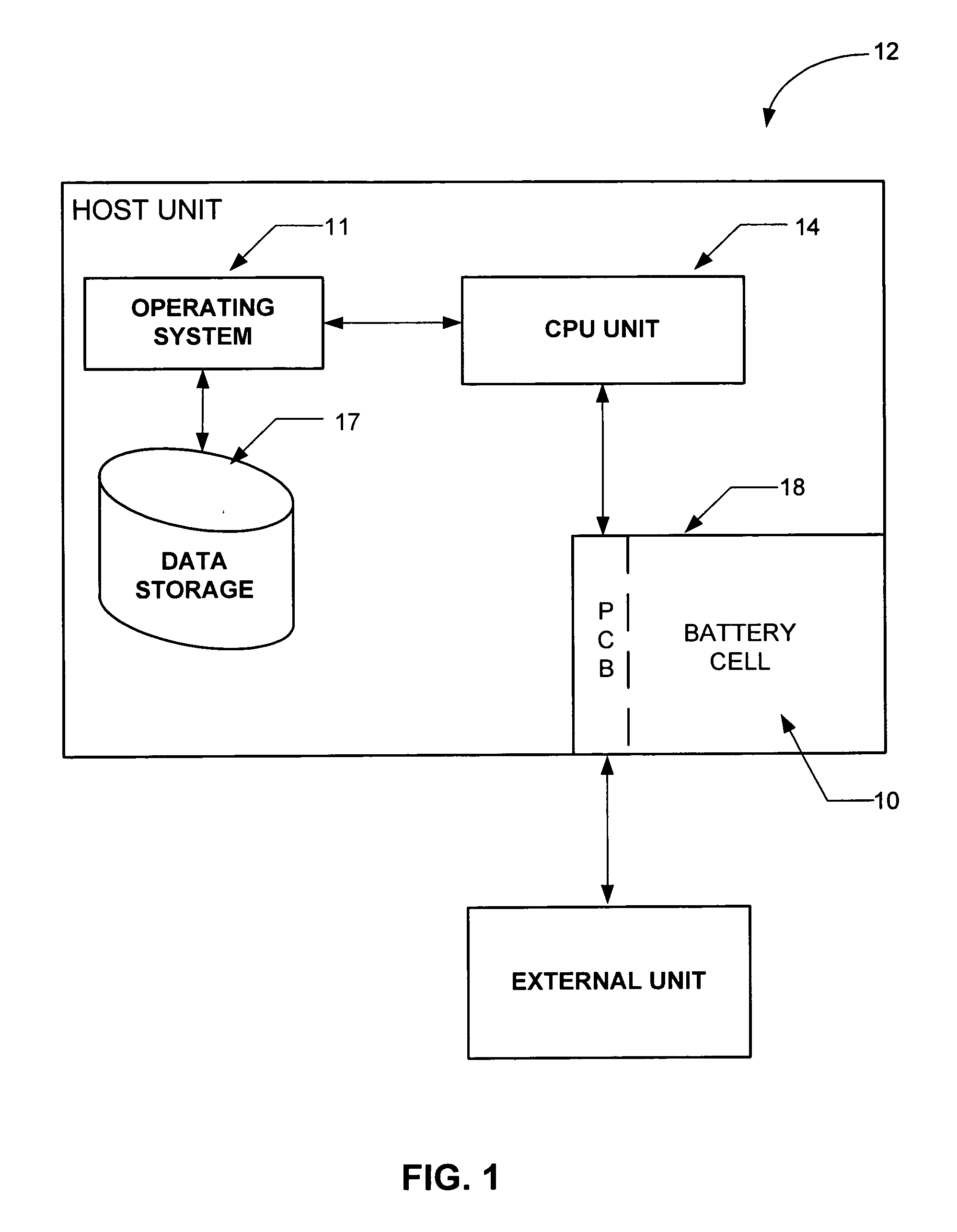
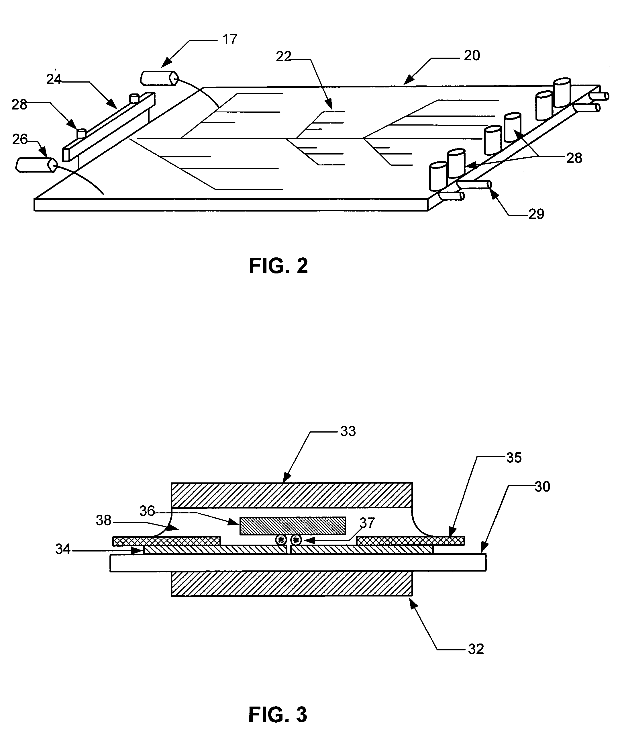
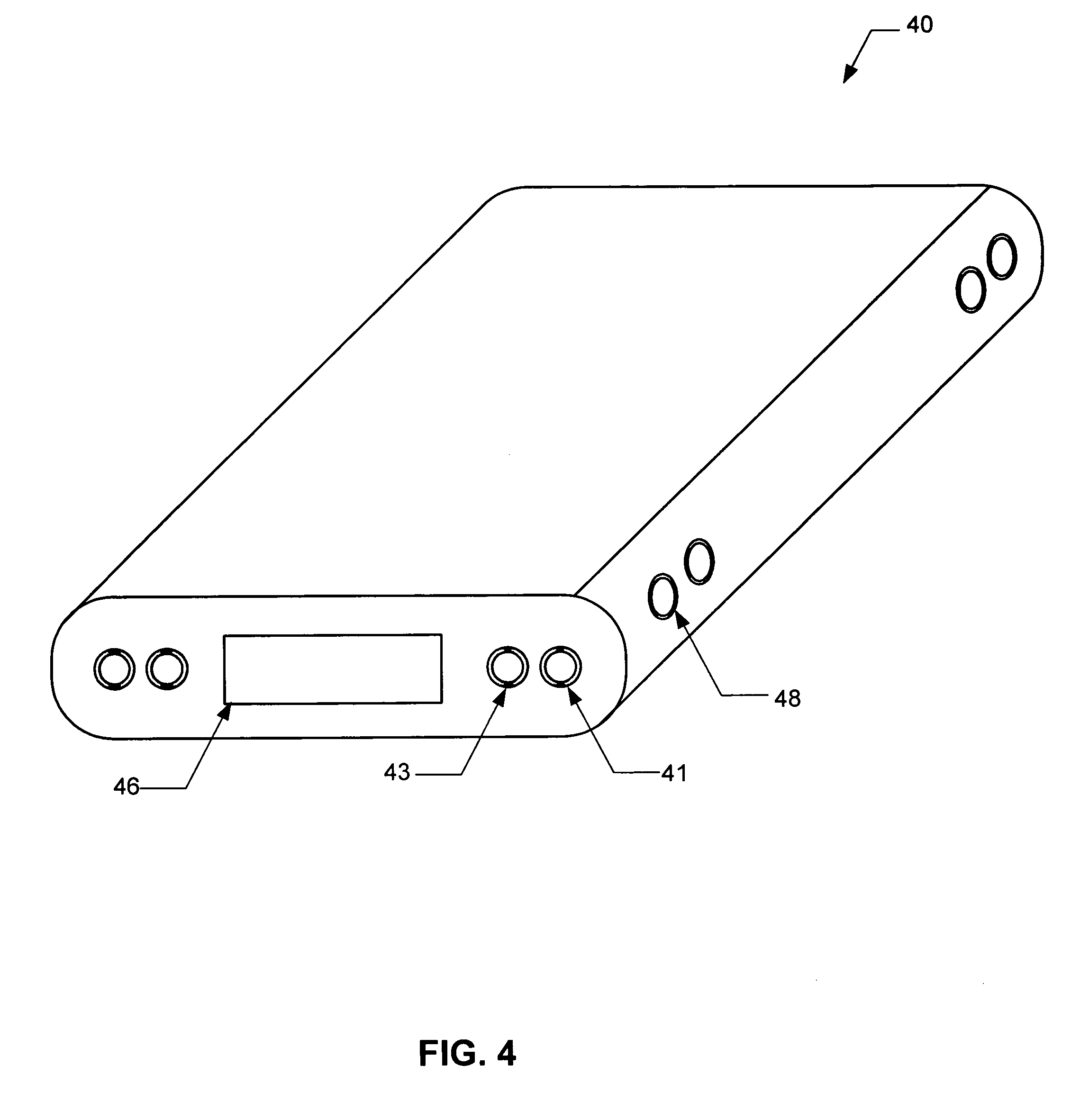
A system and method for providing a communication port integral with a battery pack assembly is disclosed. The system provides a pathway between an external unit and a host unit via a printed circuit board of the battery pack. The battery pack can include communication ports mounted on the printed circuit board for interfacing with external units. The printed circuit board further includes a substrate(s) formed with a predetermined wiring pattern electrically and / or mechanically joined to the CPU of the host unit, as well as the battery cell(s).

Description

CROSS-REFERENCE TO RELATED APPLICATIONS [0001] This application is a continuation of U.S. Ser. No. 10 / 610,225, filed Jun. 30, 2003, and entitled BATTERY PACK WITH BUILT IN COMMUNICATION PORT. This application is incorporated herein by reference.FIELD OF THE INVENTION [0002] The present invention relates generally to a battery pack assembly and in particular to a battery pack system having a built in communication port that employs a printed circuit board for transferring data to a host unit. BACKGROUND OF THE INVENTION [0003] Typically there is a desire to reduce size of electronic units, while lowering associated assembly costs and improving their overall ruggedness. In particular, many electronic units, such as; hand hold mobile terminals, communication units, and the like have various assembly costs and are generally susceptible to damage during employment in harsh environments. Such units are generally assembled by enclosing internal electrical components, such as a central proc...

Claims


Application Information

Patent Timeline
Patent Type & Authority Applications(United States)
IPC IPC(8): H02J7/00G06F1/16G06F1/26G11C7/00H01M2/10H01M10/42H01M10/44H05KH05K7/20
CPCG06F1/1613G06F1/1632G06F1/1635G06F1/266H01M2/1055H01M10/4207H01M10/425H01M10/4257H01M10/44H02J7/0004H02J7/00036H02J7/00047Y02E60/10H01M50/213H02J7/00H05K7/20
Inventor KOGAN, EDUARDYAKHNICH, VLADIMIR
Owner SYMBOL TECH LLC
Learn More