
Image sensor, image capturing apparatus, and image processing method

a technology of image sensor and image processing method, which is applied in the field of image sensors, can solve the problems of deterioration of s/n ratio, small compensation effect, and decrease in number, and achieve the effect of high sensitivity, and improving the effective sensitivity of image sensors

Inactive Publication Date: 2006-06-08
KONICA MINOLTA PHOTO IMAGING
View PDF4 Cites 85 Cited by
  • Summary
  • Abstract
  • Description
  • Claims
  • Application Information

AI Technical Summary

Benefits of technology

[0010] According this aspect of the invention, the effective sensitivity of the image sensor can be improved compared to the image sensors in which only color pixels where color filters are disposed are arranged and the conventional image sensors in which the sum total of the monochrome pixels is equal to or smaller than the sum total of the color pixels.
[0011] Consequently, since the effective sensitivity of the image sensor is improved, photographing with high sensitivity can be performed, so that a beautiful image with an excellent (high) S / N ratio can be obtained.

Problems solved by technology

Consequently, it is frequently necessary to emit flash light to ensure a necessary light reception amount, so that various problems arise such that power consumption increases to decrease the number of images that can be taken, that when a so-called camera shake compensation function is provided, the effect of compensation is small even though the camera shake compensation is performed and that the S / N ratio deteriorates (decreases) due to an increase in the amplification factor of the pixel signal obtained from each pixel.
However, according to the art of the patent document 1, since the pixels having no color filter are only a half of all the pixels of the image sensor, a significant improvement in effective sensitivity cannot be expected.

Method used


Image

  • Image sensor, image capturing apparatus, and image processing method
  • Image sensor, image capturing apparatus, and image processing method
  • Image sensor, image capturing apparatus, and image processing method

Examples


Embodiment Construction

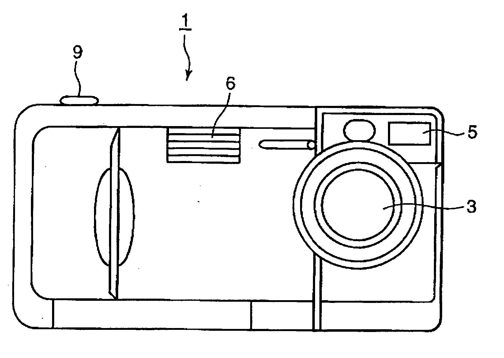
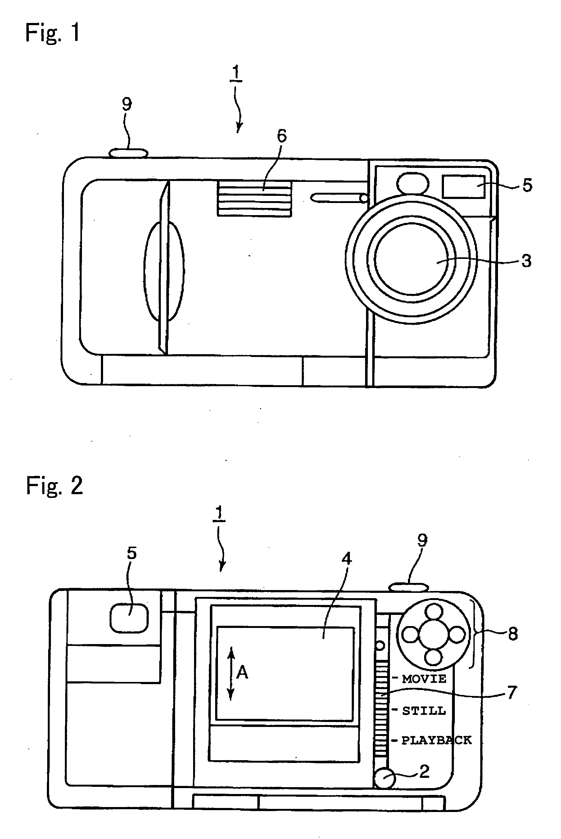
[0043] A first embodiment of the present invention will be described. FIG. 1 is a front view of an image capturing apparatus 1. FIG. 2 is a rear view of the image capturing apparatus 1.

[0044] As shown in FIGS. 1 and 2, the image capturing apparatus 1 is provided with a power button 2, an optical system 3, an LCD (liquid crystal display) 4, an optical viewfinder 5, a built-in flash 6, a mode setting switch 7, a quadruple switch 8 and a shutter button 9.

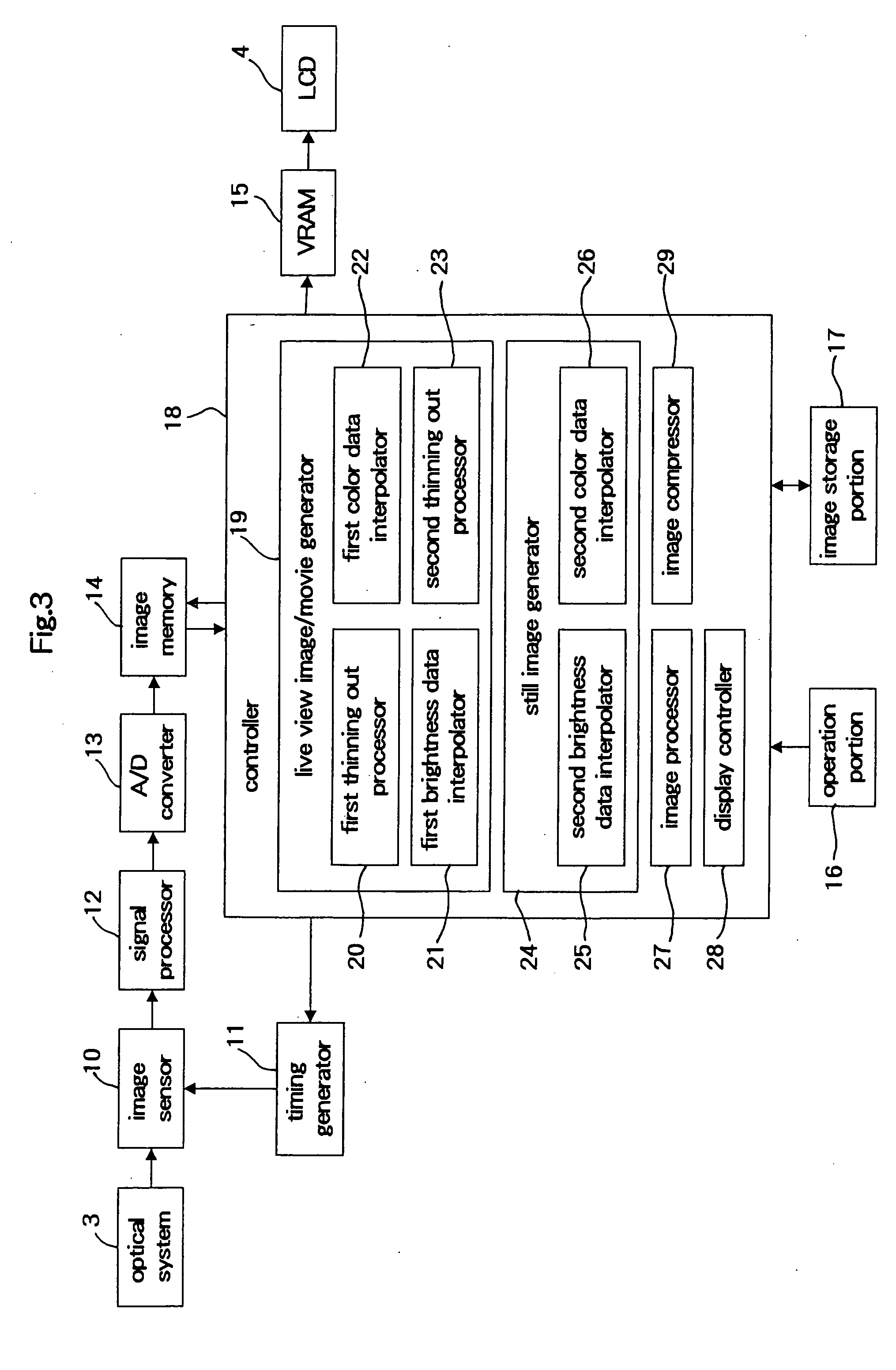
[0045] The power button 2 is for turning on and off the image capturing apparatus 1. The optical system 3 comprises a zoom lens and a non-illustrated mechanical shutter, and forms an optical image of the subject on the image capturing surface of an image sensor 10 (see FIG. 3) such as a CCD (charge coupled device).

[0046] The LCD 4 is for displaying a live view image and images recorded in an image storage portion 17 described later (see FIG. 3) (recorded image), and playing back the images recorded in the image storage portion. Inst...


PUM


Abstract

An image sensor of present invention comprising a plurality of pixels arranged in a matrix and having pixels where at least three kinds of color filters are disposed, color pixels where the color filters are disposed and monochrome pixels where no color filter is disposed are provided, the sum total of the monochrome pixels is larger than the sum total of the color pixels, and when pixels including a predetermined number of color pixels for each kind of color filter constitute one group, the color pixels or the pixels of the groups are dispersedly disposed with the monochrome pixels in between. Compared to the image sensors in which only color pixels where color filters are disposed are arranged and the conventional image sensors in which the sum total of the monochrome pixels is equal to or smaller than the sum total of the color pixels, the effective sensitivity of the image sensor can be improved, so that photographing with high sensitivity can be performed and a beautiful image with an excellent (high) S / N ratio can be obtained.

Description

[0001] This application is based on Japanese Patent Application No. 2004-353957 filed in Japan on 7 Dec. 2004, the entire content of which is hereby incorporated by reference. FIELD OF THE INVENTION [0002] The present invention relates to the technical field of an image sensor comprising a plurality of pixels arranged in a matrix, and more particularly, to an image sensor having color pixels where color filters are disposed and monochrome pixels where no color filter is disposed, an image capturing apparatus provided with the image sensor, and an image processing method using the pixel signals obtained from the image sensor. DESCRIPTION OF RELATED ART [0003] Generally, in an image sensor of a Bayer arrangement in which color filters of, for example, R (red), G (green) and B(blue) having different spectral characteristics are disposed at a ratio of 1:2:1, since the light directed to the photoelectrically conversion portions of the pixels is attenuated by the color filters, the effect...

Claims


Application Information

Patent Timeline
Patent Type & Authority Applications(United States)
IPC IPC(8): H04N5/14H04N9/73H04N9/64H04N23/12H04N25/00H04N25/73
CPCG06T3/4015H04N9/045H04N2209/047H04N23/843H04N25/134
Inventor KIDO, TOSHIHITO
Owner KONICA MINOLTA PHOTO IMAGING
Learn More