Image pickup apparatus

a pickup apparatus and image technology, applied in the field of image pickup apparatus, can solve the problems of complex circuit configuration and short exposure amount of focus detection pixels, and achieve the effect of improving the effective sensitivity

Inactive Publication Date: 2011-06-16
CANON KK
View PDF23 Cites 13 Cited by
  • Summary
  • Abstract
  • Description
  • Claims
  • Application Information

AI Technical Summary

Benefits of technology

[0009]The present invention provides an image pickup apparatus capable of improving effective sensitivity and a low-brightness detection limit of focus detection pixels without using any complex circuit configuration.

Problems solved by technology

Especially, when the focus detection is carried out while obtaining a moving image of a low-brightness object, a detection rate (frame rate) of the moving image is high, generally 30 fps to 60 fps, and hence a shortage occurs in exposure amount of the focus detection pixels if the focus detection pixels are exposed at the same rate.
Moreover, in the image pickup apparatus disclosed in Japanese Patent Laid-Open No. 2005-295381, the outputs from the image pickup pixels and measuring pixels are processed by the different signal processing circuits, and hence a circuit configuration is complex as compared with a case where signals from the image pickup pixels and measuring pixels are processed by one signal processing circuit.

Method used


Image

  • Image pickup apparatus
  • Image pickup apparatus
  • Image pickup apparatus

Examples


embodiment 1

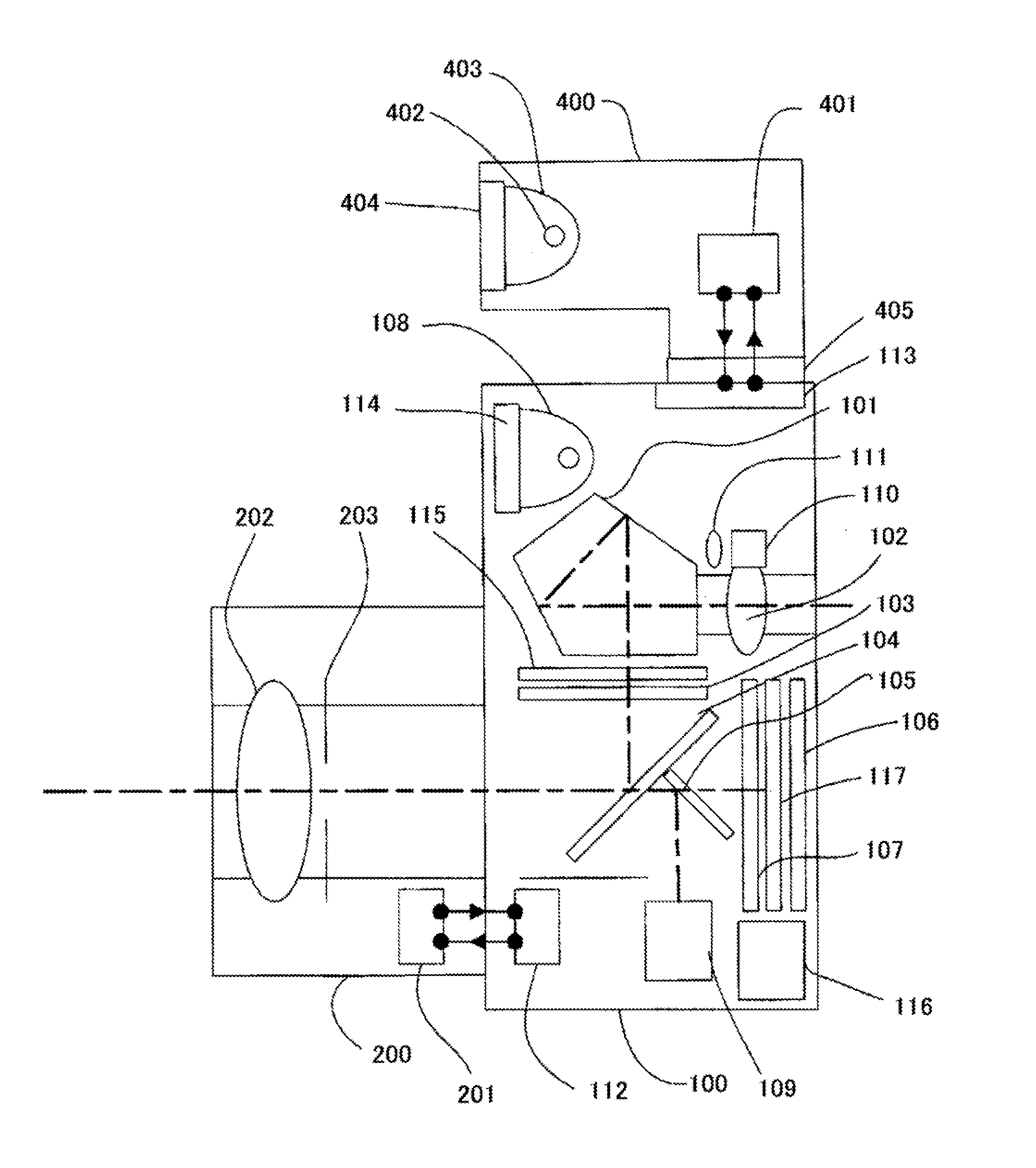
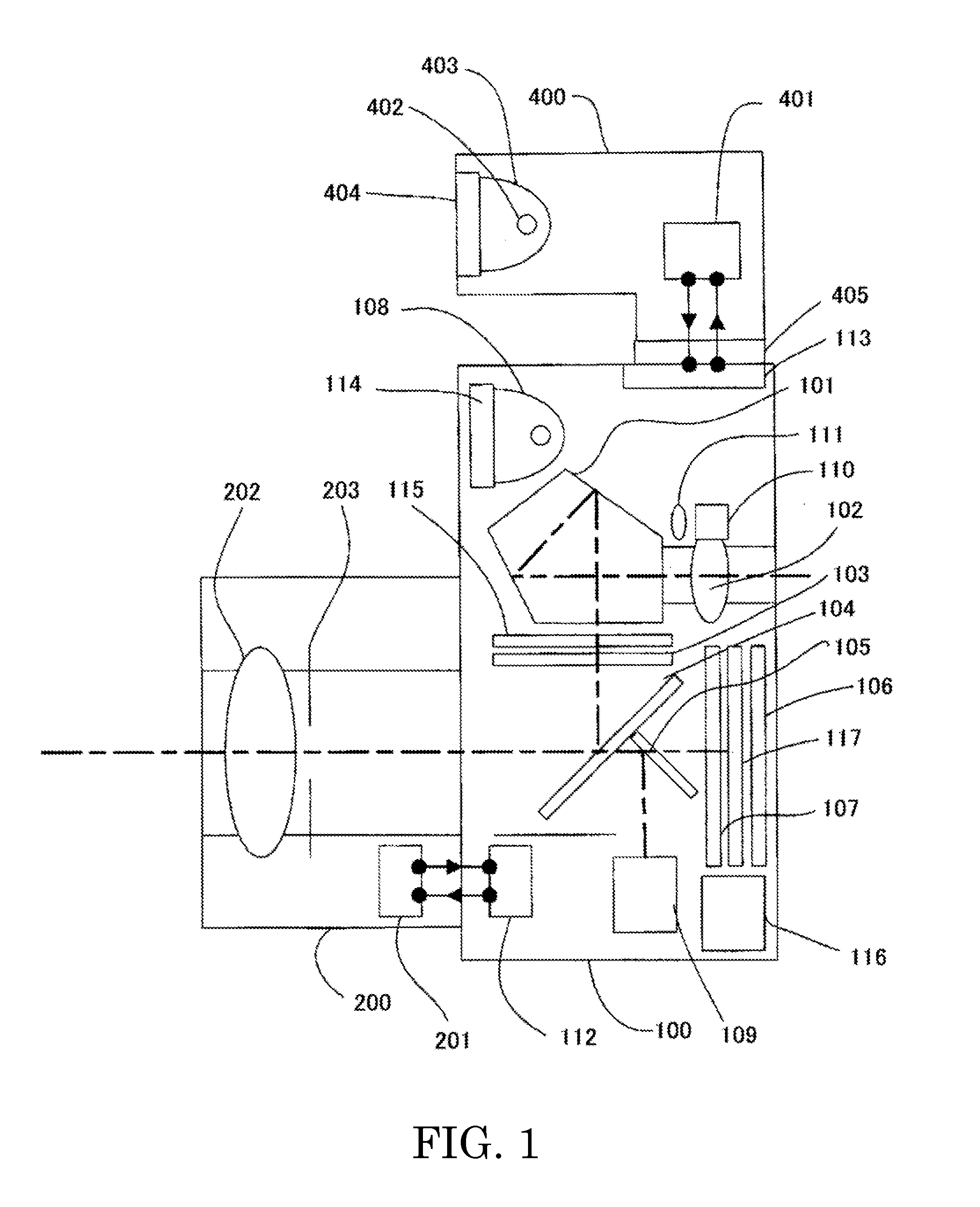
[0028]FIG. 1 shows a configuration of a single lens reflex digital camera as an image pickup apparatus which is a first embodiment (Embodiment 1) of the present invention. In FIG. 1, reference numeral 100 denotes a camera body. Reference numeral 101 denotes an optical viewfinder forming an erected normal image, reference numeral 102 denotes an eyepiece lens, and reference numeral 103 denotes a viewfinder screen.

[0029]Reference numeral 104 denotes a main half mirror (hereinafter, referred to as “main mirror”) which deflects a light flux from an image pickup optical system, which will be described later, to the viewfinder optical system. Reference numeral 105 denotes a sub-mirror which deflects the light flux that has passed through the main mirror 104 to a focus detection unit, which will be described later. The main mirror 104 and the sub-mirror 105 constitute an optical path dividing optical system. Reference numeral 106 denotes an image pickup element such as a CCD sensor or a CMO...

embodiment 2

[0112]A second embodiment (Embodiment 2) of the present invention will be described bellow. Descriptions in this embodiment similar to those of Embodiment 1 will be omitted.

[0113]FIGS. 11A and 11B show a case where a monitor pixel different from the image pickup pixel and the focus detection pixel is added to the arrangement and structure, which are shown in FIGS. 4A and 4B in Embodiment 1, of the focus detection pixels for performing the pupil division in the horizontal direction (lateral direction) of the image pickup optical system. FIG. 11B shows a D-D section of a focus detection pixel SHA and a monitor pixel SM shown in FIG. 11A.

[0114]As in the case of an output signal of the focus detection pixel SHA, an output signal of the monitor pixel SM is not used for image generation. Thus, in the monitor pixel SM, as in the case of the focus detection pixel SHA, a transparent (white) film CFW is provided in place of a color film. In order to match sensitivity of the monitor pixel SM w...

embodiment 3

[0133]A third embodiment (Embodiment 3) of the present invention will be described bellow. Descriptions in this embodiment similar to those in Embodiment 1 will be omitted.

[0134]A flowchart of FIG. 13 shows charge accumulation control processing of an image pickup element 106 in a camera of this embodiment. Description will be made of a case where output signals (pixel signals) of focus detection pixels are added by electrical hardware. A camera microprocessor 112 executes the charge accumulation control processing according to a computer program.

[0135]At Step 1600, the camera microprocessor 112 starts drive of the image pickup element 106 (that is, image pickup) via an image pickup circuit 11. Subsequent processes of S1610 to S1650 are the same as those of S1010 to S1050 in Embodiment 1. When determining at S1650 that image pickup is being performed (that is, during image pickup), the camera microprocessor 112 proceeds to S1660. When determining that image pickup is not being perfo...


PUM


Abstract

The image pickup apparatus includes an image pickup element 106 including image pickup pixels photoelectrically converting an object image formed by a light flux from an image pickup optical system 202 and focus detection pixels photoelectrically converting two images formed by two divided light fluxes of the light flux from the image pickup optical system. The apparatus further includes an image generator 112 generating an image based on first pixel signals, a focus controller 112 performing focus control for the image pickup optical system based on second pixel signals. A signal processor 112 outputs signals read out from the image pickup pixels after each charge accumulation operation of the image pickup pixels for a predetermined time period as the first pixel signals, and outputs signals obtained by plural charge accumulation operations of the focus detection pixels as the second pixel signals.

Description

TECHNICAL FIELD[0001]The present invention relates to an image pickup apparatus such as a digital camera and a video camera, and particularly to an image pickup apparatus which performs phase difference detection using an image pickup element.BACKGROUND ART[0002]As an AF (auto focus) system of an image pickup apparatus, there is known a TTL phase difference detection system. In the TTL phase difference detection system, part of a light flux from an image pickup optical system is divided into two light fluxes, and a shift amount (phase difference) between two images formed by the two divided light fluxes is obtained. Then, a defocus amount indicating a focus state of the image pickup optical system is calculated based on the phase difference, and a driving amount of a focus lens necessary for approaching the defocus amount to 0 to obtain an in-focus state is calculated.[0003]There has been proposed an image pickup apparatus which performs AF using such a TTL phase difference detectio...

Claims


Application Information

Patent Timeline
Patent Type & Authority Applications(United States)
IPC IPC(8): H04N5/335
CPCG02B7/34H04N5/3696H04N5/23212G03B13/36H04N23/672H04N25/702H04N25/134
Inventor NAKAGAWA, KAZUYUKI
Owner CANON KK
Why Eureka
Try Eureka