Frequency phase correction system

a frequency phase correction and frequency phase technology, applied in the field of global positioning (“ gps”) receivers, can solve the problems of inability of emergency response centers to automatically determine and communicate their location, inability to automatically determine and communicate the location of conventional wireless devices without position determination capability, and inability to achieve the emergency response center's location. , to achieve the effect of improving the drift rate correction factor, reducing signal levels, and increasing the effective sensitivity of gps receivers

Inactive Publication Date: 2005-07-28
CSR TECH INC
View PDF99 Cites 44 Cited by
  • Summary
  • Abstract
  • Description
  • Claims
  • Application Information

AI Technical Summary

Benefits of technology

[0036] Thus, as a further advantage of the invention, if the reference frequency used to get a lock on the GPS satellite signal is off by a certain amount, which is referred to as frequency error, the invention determines the frequency error and its drift rate, and uses this characterization data to allow integration of the incoming GPS signal to occur over a longer period of time while maintaining coherence with the incoming signal. As a result, this increases the effective sensitivity of the GPS receiver, allowing detection and measurement of lower signal levels than may otherwise be detected with conventional systems.
[0037] The present invention may be implemented in an example of an implementation that provides higher order characterization data to be determined such as, for example, phase jerk. Utilizing these higher-order characterization data allow the receiver to inject an improved drift rate correction factor into the correction algorithm during an interval of processing time. This characterization data, including the higher-order characterization data, can be projected in time to allow application to a future processing interval. Additionally, measurements of varying measurement quality and varying sampling intervals can be combined.
[0038] Other systems, methods, features and advantages of the invention will be or will become apparent to one with skill in the art upon examination of the following figures and detailed description. It is intended that all such additional systems, methods, features and advantages be included within this description, be within the scope of the invention, and be protected by the accompanying claims.

Problems solved by technology

In practice, however, this is rarely achievable, and four satellites are used to compute a three dimensional fix with the user clock error removed, or three satellites are used to compute a two-dimensional, horizontal fix (in latitude and longitude) given an assumed altitude.
Unfortunately, because wireless devices, such as cellular telephones, are not hard wired into the PSTN and can move about, the emergency response center cannot determine their location as is possible with automatic-number-identification (“ANI”) techniques available for use with land-line calls.
Furthermore, conventional wireless devices without a position determination capability are unable to automatically determine and communicate their location without a person actively entering or describing their location.
If instead, an E911 call is placed from a wireless device such as a cellular telephone, the E911 reception center receives the call but cannot determine the origin of the call without information provided by the person who made the call.
Unfortunately, typical cell sites in a wireless network system may cover an area with approximately a 30-mile diameter.
But, this still results in an area covering multiple miles.
Therefore, emergency personnel cannot be dispatched to the scene without more information.
The integration of GPS capabilities with a wireless communication device, however, presents some challenges.
For example, due to their mobile nature and because mobile-device designers are striving for smaller packaging as well as longer battery life, wireless communication devices often find themselves in areas where the signal strength of received GPS signals is weaker than desired.
As a result, it may be a challenge for the GPS receiver to receive and lock onto the GPS signal received from the GPS satellites.

Method used


Image

  • Frequency phase correction system
  • Frequency phase correction system
  • Frequency phase correction system

Examples


Embodiment Construction

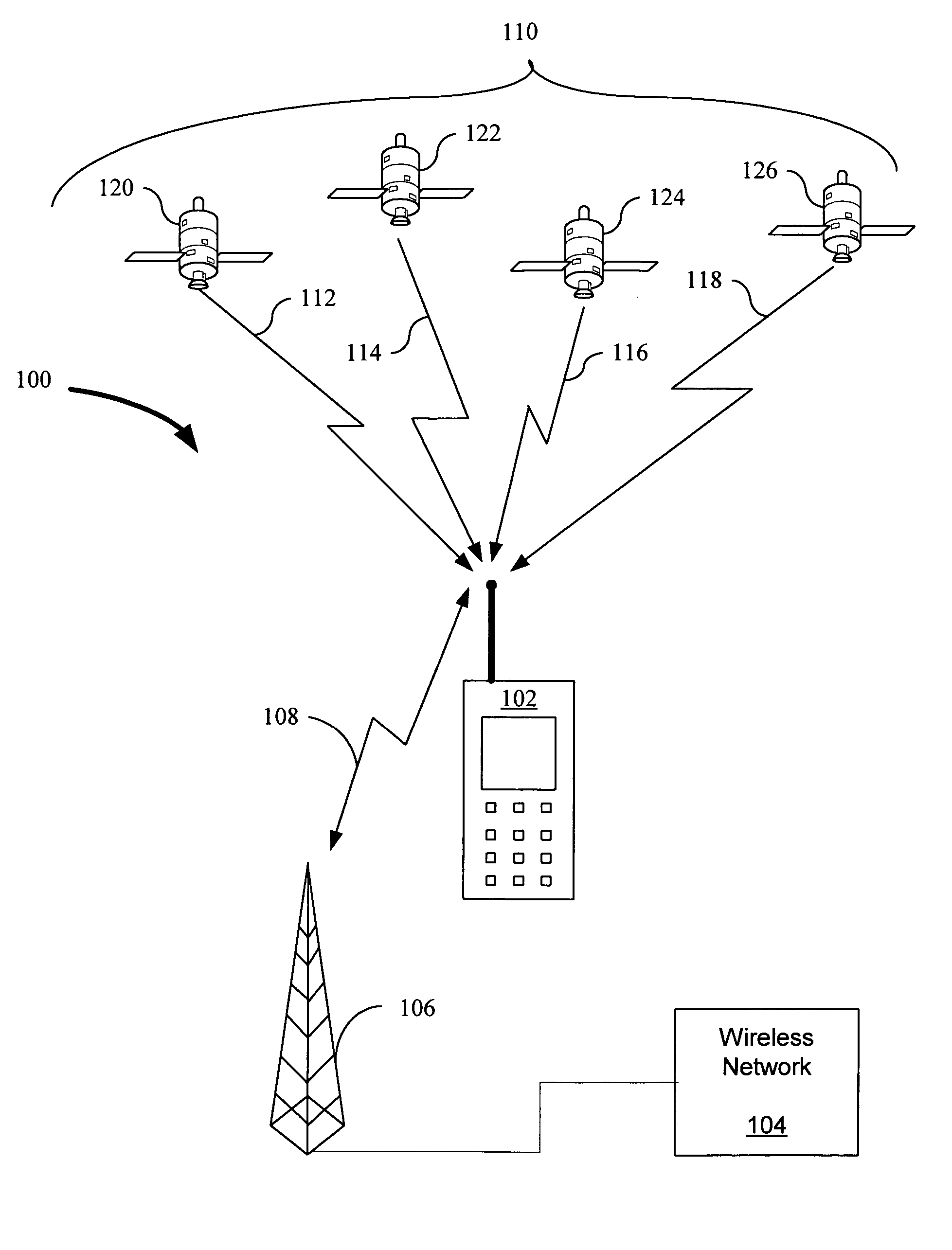
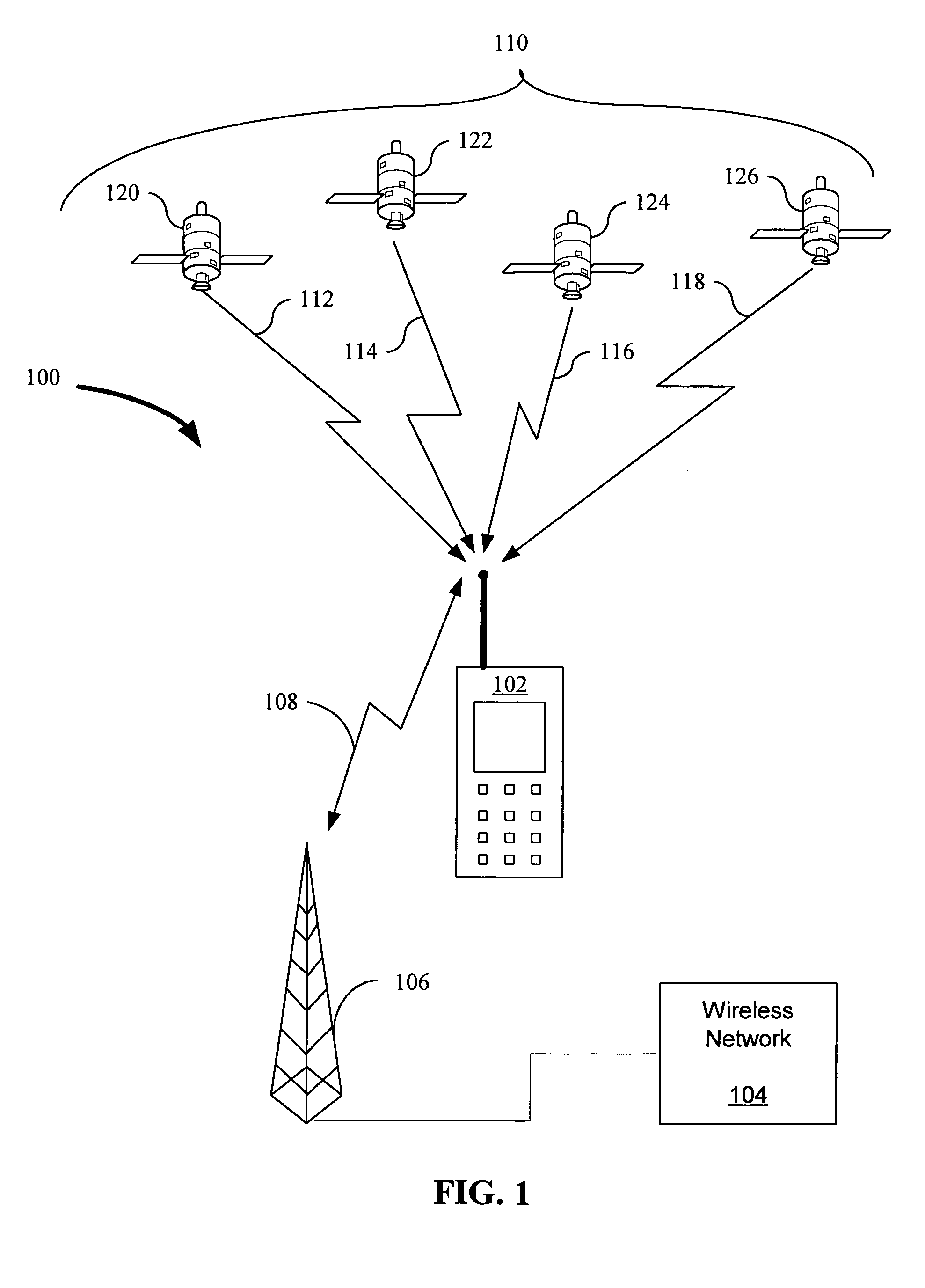
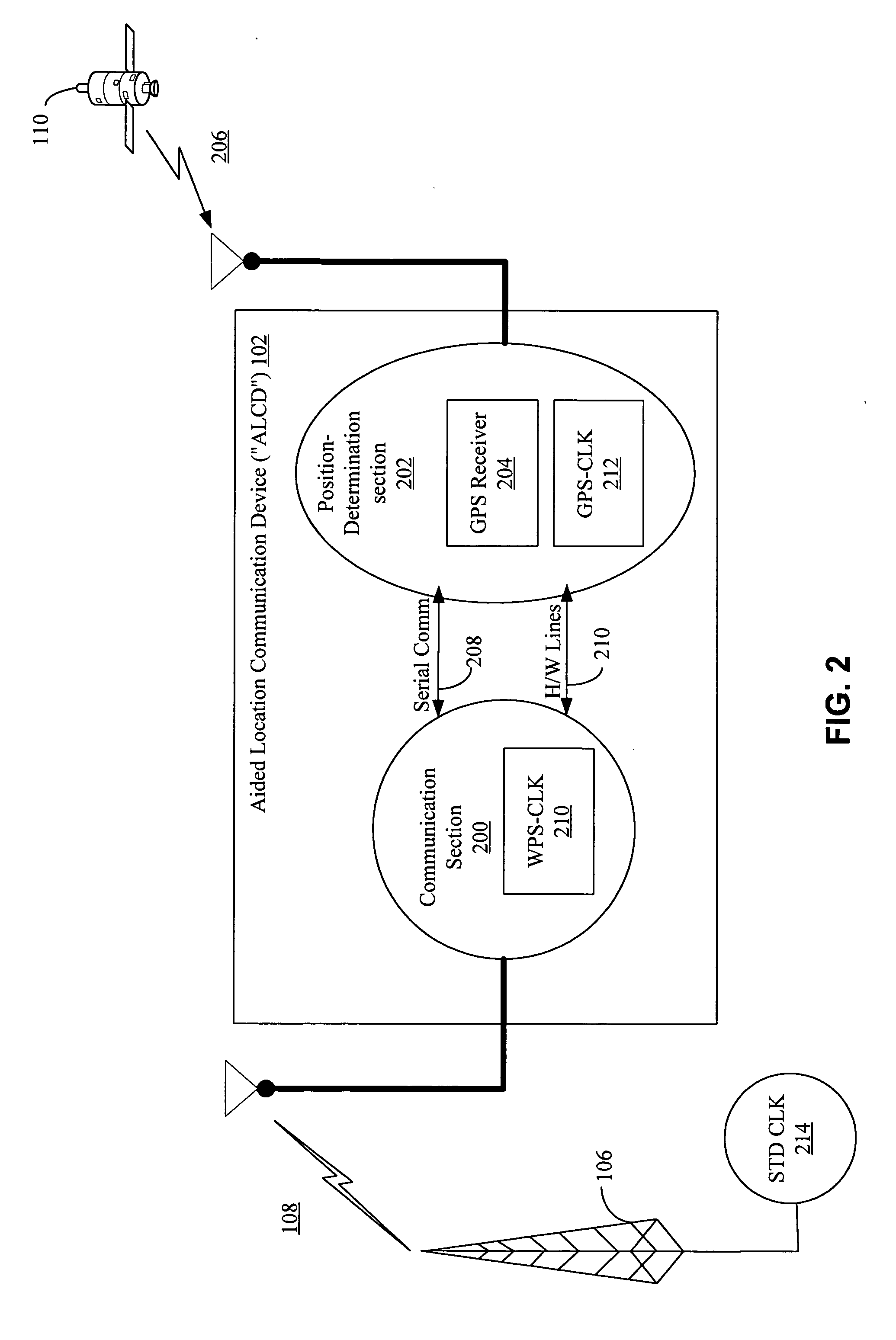
[0049] In the following description of the preferred and various alternative embodiments, reference is made to the accompanying drawings that form a part hereof, and in which is shown by way of illustration a specific embodiment in which the invention may be practiced. It is to be understood that other embodiments may be utilized and structural changes may be made without departing from the spirit and scope of this invention.

[0050] The invention is described with reference to various functional block diagrams, which illustrate possible applications of and embodiments of the invention from a functional perspective. These functional block diagrams should not be interpreted to imply or otherwise require a particular physical architecture in accordance with the partitioning of the functionality depicted therein. Instead, it will be appreciated by one of ordinary skill in the art that various alternative physical architectures (whether hardware, software or a combination thereof) can be...


PUM


Abstract

A frequency phase correction system and method are described that provides a receiver with a greater ability to lock onto relatively weak radio frequency signals by determining and estimating an amount of frequency error in a local frequency reference of the receiver, and using the error estimate to maintain frequency coherence with a received signal, thereby allowing tracking over a longer period of time, enabling longer integration times to capture weaker signals without losing frequency coherence.

Description

CROSS REFERENCE TO RELATED APPLICATIONS [0001] This application is a continuation-in-part of U.S. patent application Ser. No. 10 / 885,507, filed Jul. 3, 2004, titled “Aided Location Communication System,” which application is incorporated into this application by reference in its entirety and which application is: [0002] (a) a continuation in part of PCT application Serial No. PCT / US03 / 16308, filed May 22, 2003, titled “Aiding in a Satellite Positioning System,” which is a continuation-in-part of U.S. patent application Ser. No. 10 / 155,614, filed May 22, 2002, titled “A Method for Aiding a Global Positioning System,” now U.S. Pat. No. 6,684,158, which is a continuation-in-part of U.S. patent application Ser. No. 09 / 795,871, filed Feb. 28, 2001, titled “Information Transfer in a Multi-mode Global Positioning System Used with Wireless Networks,” now U.S. Pat. No. 6,427,120, which claims priority under Section 119(e) to U.S. Provisional Application Ser. No. 60 / 225,076, filed Aug. 14, 20...

Claims


Application Information

Patent Timeline
Patent Type & Authority Applications(United States)
IPC IPC(8): H04B17/40G01S1/00G01S5/02G01S19/05G01S19/23H04W64/00
CPCG01S5/021G01S19/05G01S19/17H03L1/022H03J7/065H03J2200/12G01S19/235
Inventor BABITCH, DANIELGRONEMEYER, STEVEN A.GARIN, LIONELPANDE, ASHUTOSHPENG, LEON KUO-LIANGZHANG, GENGSHENGVANTALON, NICOLAS PATRICK
Owner CSR TECH INC
Why Eureka
Try Eureka