Transmission signal generating unit and radar transmission device using the same

a technology of transmission signal and generating unit, which is applied in the direction of modulation, using reradiation, instruments, etc., can solve the problem of unknown performance limit, and achieve the effect of suppressing spurious components and lowering the signal level

Active Publication Date: 2007-11-29
KK TOSHIBA
View PDF6 Cites 0 Cited by
  • Summary
  • Abstract
  • Description
  • Claims
  • Application Information

AI Technical Summary

Benefits of technology

[0010]In order to suppress the spurious components, a tapering is applied to edge parts of the waveform of a transmission signal, however, the more the spurious components are suppressed, the lower the level of the signal becomes.

Problems solved by technology

However, there is no conventional method that shows the limit and therefore the feasible limit of the performance has been unknown.

Method used


Image

  • Transmission signal generating unit and radar transmission device using the same
  • Transmission signal generating unit and radar transmission device using the same
  • Transmission signal generating unit and radar transmission device using the same

Examples


Embodiment Construction

[0018]There will be below explained a transmission signal generating unit according to an embodiment of the present invention in detail with reference to several figures.

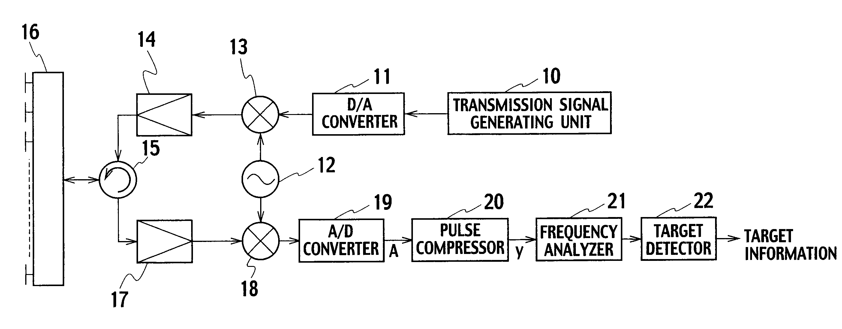
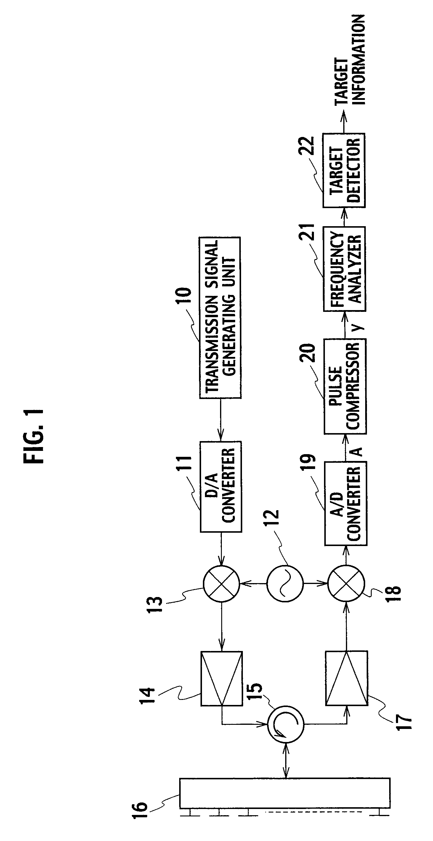
[0019]FIG. 1 shows the schema of a radar device employing the transmission signal generating unit according to the embodiment of the present invention.

[0020]The radar device comprises a transmission signal generating unit 10, a D / A converter 11, a local oscillator 12, a transmitting side mixer 13, a transmission signal amplifier 14, a circulator 15, an antenna 16, a received signal amplifier 17, a receiving side mixer 18, an A / D converter 19, a pulse compressor 20, a frequency analyzer 21, and a target detector 22.

[0021]The transmission signal generating unit 10 generates a digital signal (pulse signal) as a transmission signal and transmits it to the D / A converter 11. The D / A converter 11 converts the transmission signal transmitted by the transmission signal generating unit 10 to an analog signal and transmits it ...


PUM


Abstract

A transmission signal generating unit has a window function calculator that generates a window function that makes all frequencies without a center frequency of an input signal and its adjacent frequencies zero and makes the signal to noise ratio of the center frequency maximum; and a transmission signal generator that generates a transmission signal whose amplitude is modulated in a shape of an envelope curve based on the window function generated by the window function calculator.

Description

BACKGROUND OF THE INVENTION[0001]1. Field of the Invention[0002]The present invention relates to a transmission signal generating unit and a radar transmission device using the same.[0003]2. Description of Related Art[0004]Since the utilization of radio waves is increasing, narrowing the frequency band of a radar signal is strongly demanded to efficiently use frequencies between various devices.[0005]In addition, suppressing the spurious components of the radar signal as low as possible has become an international issue. The development of technology to narrow the frequency band and to suppress the spurious components enables to operate the radars within a narrower frequency band. This will contribute to solve the shortage of frequencies.[0006]As a solution for these problems, a low-power pulse compression radar is put to practical use.[0007]Japanese Patent Publication Laid-open No. H4-357485 shows a radar signal processing device employing a pulse compression method. This radar sig...

Claims


Application Information

Patent Timeline
Patent Type & Authority Applications(United States)
IPC IPC(8): G01S13/00G01S7/282
CPCG01S7/023H03C1/00G01S13/28G01S7/282
Inventor SHINONAGA, MITSUYOSHI
Owner KK TOSHIBA
Why Eureka
Try Eureka