
Magnetic head with soft magnetic shield and magnetic storage

a magnetic shield and head technology, applied in the field of magnetic heads and magnetic storage apparatuses, can solve the problems of large amount of leakage flux in the chassis, low robustness of the external field in principle, and high sensitivity of the double layered perpendicular recording system to the external field, so as to improve the robustness of the floating field and high reliability

Inactive Publication Date: 2006-06-08
HITACHI GLOBAL STORAGE TECH NETHERLANDS BV
View PDF14 Cites 12 Cited by
  • Summary
  • Abstract
  • Description
  • Claims
  • Application Information

AI Technical Summary

Benefits of technology

[0008] It is a feature of the invention to effectively improve external field robustness in the double layered perpendicular recording system without the modification of the device structure.
[0011] The invention can provide a magnetic storage apparatus with high reliability that enables improvement of the floating field robustness in the use of a double layered perpendicular recording medium with a soft magnetic under layer. In particular, the invention has an advantage in the application of a small-sized magnetic storage apparatus that is not susceptible to modification of its structure.

Problems solved by technology

The double layered perpendicular recording system has high sensitivity and low robustness to the external field in principle.
The improvement of these features is limited even if the structures and magnetic characteristics of the magnetic head and recording medium are modified.
In the method for attaching the shield outside the drive chassis, a distance diverted is so long that the magnetic resistance becomes large, which results in a large amount of leakage flux in a chassis.
This disadvantageously leads to an increase in size and weight of the device.
The attachment of the shield onto a part other than the conventional components often needs modification of the device structure, which might result in increased costs related to the development of the device.
This shield is to decrease the magnetic fluxes from adjoining tracks in reproducing, and hence is insufficient to obtain an effect on the external field.
Thus, the problem of erasing of recorded data due to the floating field or the like is not caused.
However, since the soft magnetic shield is not shaped so as to concentrate the fluxes on the medium-facing surface, unlike in the case of the main-pole for recording, the single soft magnetic shield itself cannot readily induce the concentration of the fluxes.

Method used


Image

  • Magnetic head with soft magnetic shield and magnetic storage
  • Magnetic head with soft magnetic shield and magnetic storage
  • Magnetic head with soft magnetic shield and magnetic storage

Examples


embodiment 1

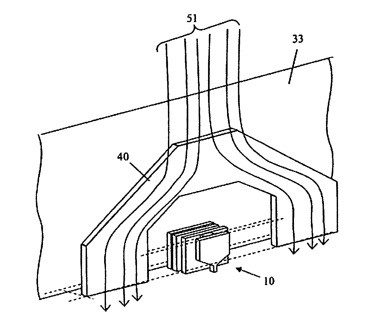
[0031] An embodiment will be explained below in which the soft magnetic shield of the invention is applied to a double layered perpendicular magnetic recording medium including a magnetic recording layer with perpendicular magnetic anisotropy and a soft magnetic under layer, and to a magnetic storage apparatus using a single pole type writer and a MR read head.

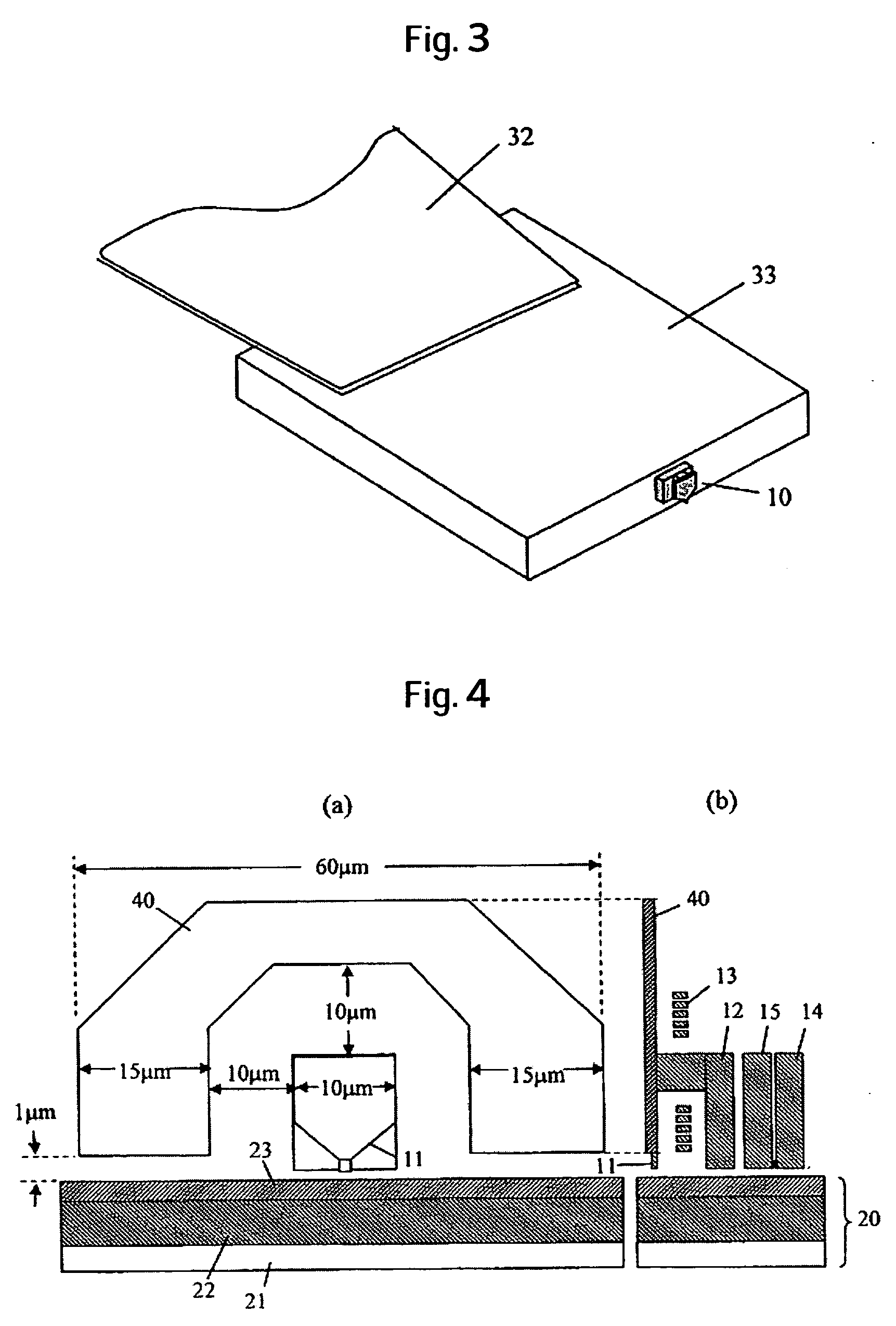
[0032]FIG. 4 is a schematic diagram illustrating an example of the structure of the magnetic head element according to the present invention. FIG. 4(a) is a plan view showing a surface including a main-pole and the soft magnetic shield, and FIG. 4(b) is a sectional view of the magnetic head. Note that the cross-section of the magnetic recording medium is schematically shown in the figure. In this embodiment, a wide part of the main-pole on its upper side has the same width and height as the return-pole, and the reader shield.

[0033] The soft magnetic shield 40 In this embodiment is formed so as to surround the main-pole 11 wh...

embodiment 2

[0038]FIG. 7 is a schematic diagram illustrating another example of the structure of a magnetic head element according to the present invention. FIG. 7(a) is a plan view showing a surface including a main-pole and a soft magnetic shield, and FIG. 7(b) is a sectional view of the magnetic head. Note that the cross-section of a magnetic recording medium is schematically shown in the figure.

[0039] In this embodiment, a thick soft magnetic shield 41 is disposed so as to surround not only the main-pole 11 for recording, but also the whole magnetic member constituting the magnetic head element. The features of the soft magnetic shield 41 other than the thickness, including the shape, are the same as in Embodiment 1. The most influence of the external field is exerted on the main-pole. However, the magnetic fluxes may be in principle concentrated on the ends of a return-pole and a reader shield, and the fluxes may flow from these magnetic members in the main-pole. For this reason, providin...


PUM

PropertyMeasurementUnit
widthaaaaaaaaaa
widthaaaaaaaaaa
distanceaaaaaaaaaa

Abstract

Embodiments of the invention avoid erasure of recorded data by concentrating stray fields on a magnetic head element. According to one embodiment, in a magnetic storage apparatus using a perpendicular recording medium with a soft magnetic under layer, a soft magnetic shield is provided so as to surround the upper parts and sides of magnetic head elements. A distance between the soft magnetic shield and the medium is shorter than that between the soft magnetic shield and the magnetic head element.

Description

CROSS-REFERENCES TO RELATED APPLICATIONS [0001] This application claims priority from Japanese Patent Application No. JP2004-351654, filed Dec. 3, 2004, the entire disclosure of which is incorporated herein by reference. BACKGROUND OF THE INVENTION [0002] The present invention relates to magnetic heads, and magnetic storage apparatus using the same. More particularly, the invention relates to a magnetic storage apparatus which comprises a magnetic head including a single pole type writer, and a double layered magnetic recording medium having a soft magnetic under layer. [0003] To enhance recording density of a magnetic disk device, a double layered perpendicular recording system is advantageous which combines a double layered perpendicular magnetic recording medium having a recording layer and a soft magnetic under layer, and a magnetic head having a single pole type writer mounted thereon. FIG. 13 is a schematic diagram illustrating the structure of the magnetic head and the medium...

Claims


Application Information

Patent Timeline
Patent Type & Authority Applications(United States)
IPC IPC(8): G11B5/41
CPCG11B5/11G11B5/1278G11B5/3116G11B5/3146G11B5/315
Inventor NISHIDA, YASUTAKATAGAWA, IKUYAMOCHIZUKI, MASAFUMIWOOD, ROGER
Owner HITACHI GLOBAL STORAGE TECH NETHERLANDS BV
Learn More