Power converter system

Active Publication Date: 2006-06-08
ANALOG DEVICES INC
View PDF37 Cites 52 Cited by
  • Summary
  • Abstract
  • Description
  • Claims
  • Application Information

AI Technical Summary

Benefits of technology

[0009] It is a further object of this invention to provide such a power converter system which is less expensive.
[0010] It is a further object of this invention to provide such a power converter system which reduces switching losses.
[0011] It is a further object of this invention to provide such a power converter system which is more reliable.
[0012] It is a further object of this invention to provide such a power converter system which is easily repeatable.
[0013] It is a further object of this invention to provide such a power converter system which is more efficient.
[0014] This invention results from the realization that an improved power conver

Problems solved by technology

However, the size of the magnetic core of the transformer prevents the power converter system from being disposed on an integrated circuit chip.
However, conventional power converter systems do not employ micro-transformers to transfer power across an isolation barrier because they cannot generate sufficient high frequencies to prevent micro-transforme

Method used


Image

  • Power converter system
  • Power converter system
  • Power converter system

Examples


Embodiment Construction

[0032] Aside from the preferred embodiment or embodiments disclosed below, this invention is capable of other embodiments and of being practiced or being carried out in various ways. Thus, it is to be understood that the invention is not limited in its application to the details of construction and the arrangements of components set forth in the following description or illustrated in the drawings. If only one embodiment is described herein, the claims hereof are not to be limited to that embodiment. Moreover, the claims hereof are not to be read restrictively unless there is clear and convincing evidence manifesting a certain exclusion, restriction, or disclaimer.

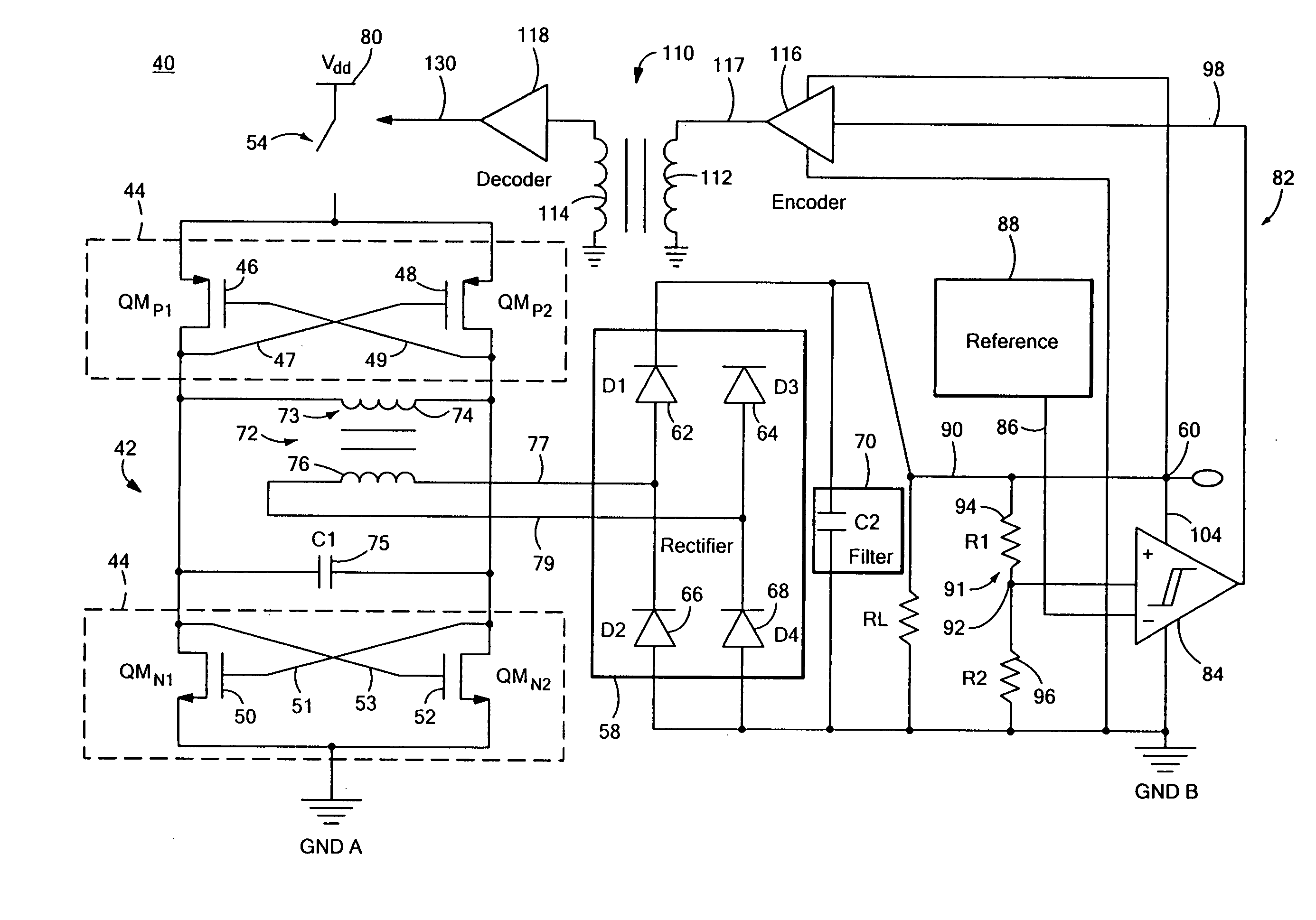
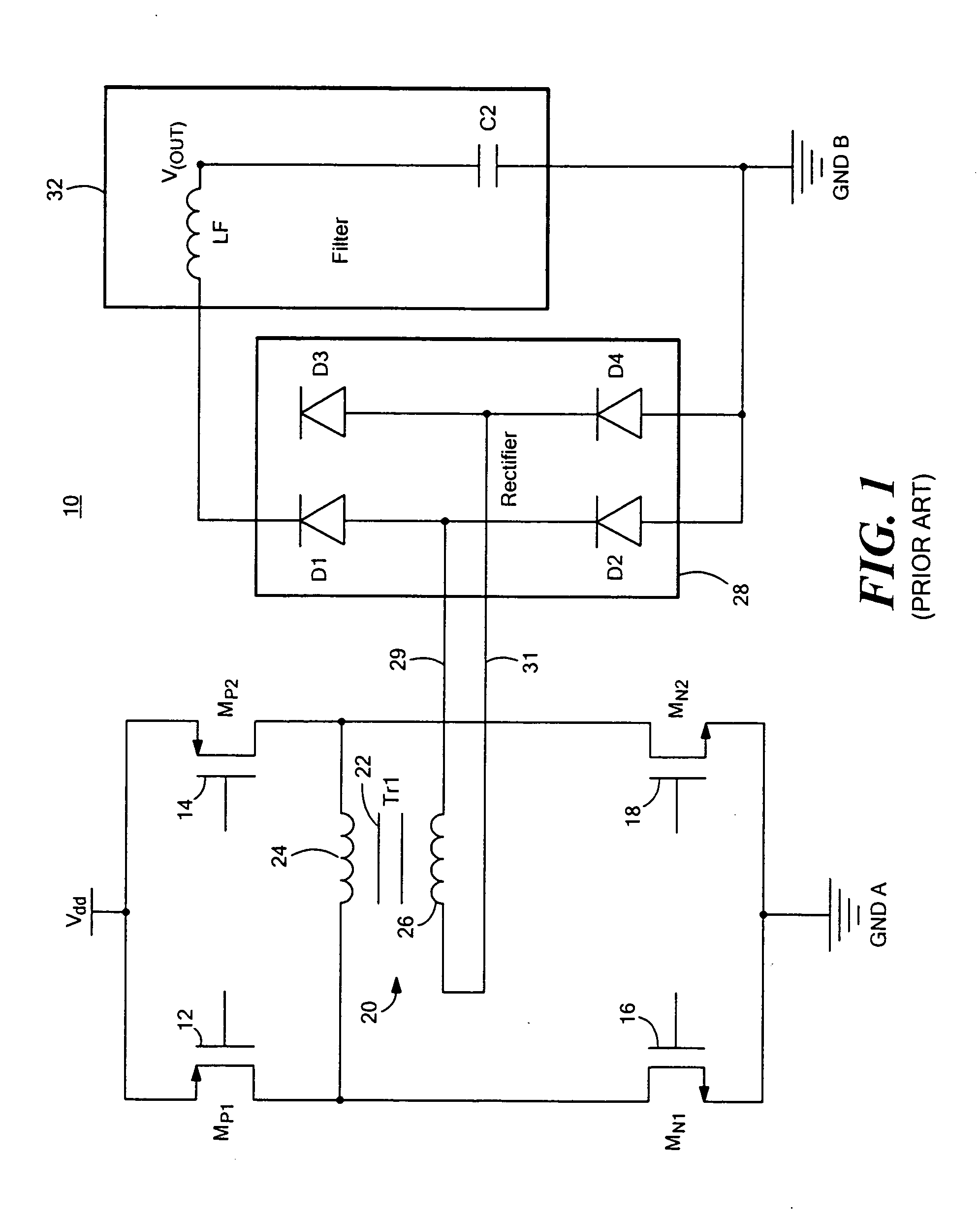
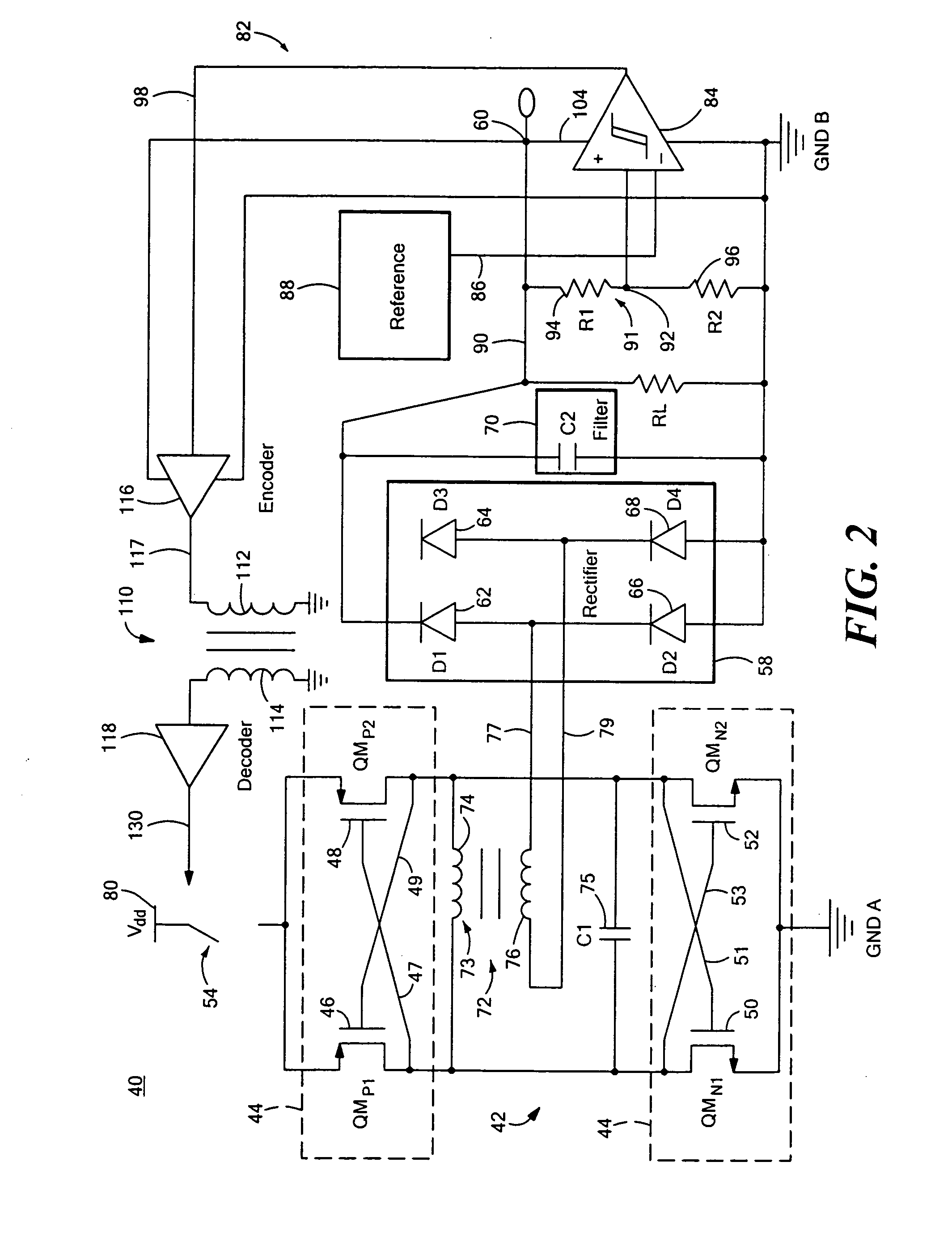
[0033] Conventional isolated power conversion system 10, FIG. 1, typically includes switches 12 (MP1), 14 (MP2), 16 (MN1) and 18 (MN2) that drive discrete transformer 20. Transformer 20 includes magnetic core 22 (Tr1), primary winding 24 and secondary winding 26. System 10 includes full bridge rectifier circuit 28 and fil...


PUM


Abstract

A power converter system including an LC oscillator circuit, an oscillator drive circuit for driving the LC oscillator circuit, a rectifier circuit coupled to the LC oscillator circuit for providing a DC output, and a switching circuit for controlling the duty cycle of the oscillator drive circuit to modulate the power in the LC oscillator circuit and the rectifier circuit.

Description

RELATED APPLICATIONS [0001] This application is a Continuation-in-Part application of U.S. patent application Ser. No. 10 / 922,504, filed Aug. 20, 2004, entitled “Power and Information Signal Transfer Using Micro-Transformers”, incorporated by reference herein.FIELD OF THE INVENTION [0002] This invention relates generally to isolated power converter systems and more particularly to an improved power converter system that transfers power across an isolation barrier using micro-transformers disposed on an integrated circuit chip. BACKGROUND OF THE INVENTION [0003] Conventional isolated power converter systems typically rely on a discrete transformer with a magnetic core and discrete diodes in a rectifier circuit to transfer power across an isolation barrier. However, the size of the magnetic core of the transformer prevents the power converter system from being disposed on an integrated circuit chip. Micro-transformers that are small in size and can be disposed on a chip, e.g., “air-co...

Claims


Application Information

Patent Timeline
IPC IPC(8): H02M3/335
CPCH02M3/33523H02M3/3387H02M3/33576H02M3/33569H02M3/33573H02M3/01H02M3/335
Inventor CHEN, BAOXINGKLIGER, RONN
Owner ANALOG DEVICES INC
Why Eureka
Try Eureka