Protocol for exchanging control data to mitigate interference problems in wireless networking

Inactive Publication Date: 2006-06-08
MICROSOFT TECH LICENSING LLC
View PDF33 Cites 75 Cited by
  • Summary
  • Abstract
  • Description
  • Claims
  • Application Information

AI Technical Summary

Benefits of technology

[0011] In one implementation, the cooperative protocol provides the framework and structure that is used for peer discovery, peer information exchange, and the transport mechanism used to deliver the protocol. According to the cooperative protocol, the locally-detected interference-related information is formatted, along with general environment information and the like, into control data, which is then distributed from the local node to a remote peer node in the wireless network that is RCS-enabled (running the robust coexistence service), whereby the remote node knows the local node's current RF environment. A similar exchange of control data occurs in the opposite direction.

Problems solved by technology

As wireless connectivity spreads, the likelihood of radio frequency (RF) activity from other bands and overlaying bands used in wireless networking bands increases for any given location, resulting in interference for a greater percentage of wireless network users.
Further, because wireless networks operate in unlicensed bands in the 2.4 GHz and 5 GHz regions of the RF spectrum, many other RF devices transmit information (or noise) on these frequencies as well, causing interference to the WLAN communication.
Examples of various sources and types of interference seen by a home wireless network may include microwave ovens, which cause slow periodic interference; cordless phones, which cause interference of a type referred to as “slow hopper;” a Bluetooth headset (causing fast hopper interference); digital spread spectrum (DSS) cordless phones, which cause constant custom waveform interference; and wireless surveillance cam

Method used


Image

  • Protocol for exchanging control data to mitigate interference problems in wireless networking
  • Protocol for exchanging control data to mitigate interference problems in wireless networking
  • Protocol for exchanging control data to mitigate interference problems in wireless networking

Examples


Embodiment Construction

Exemplary Operating Environment

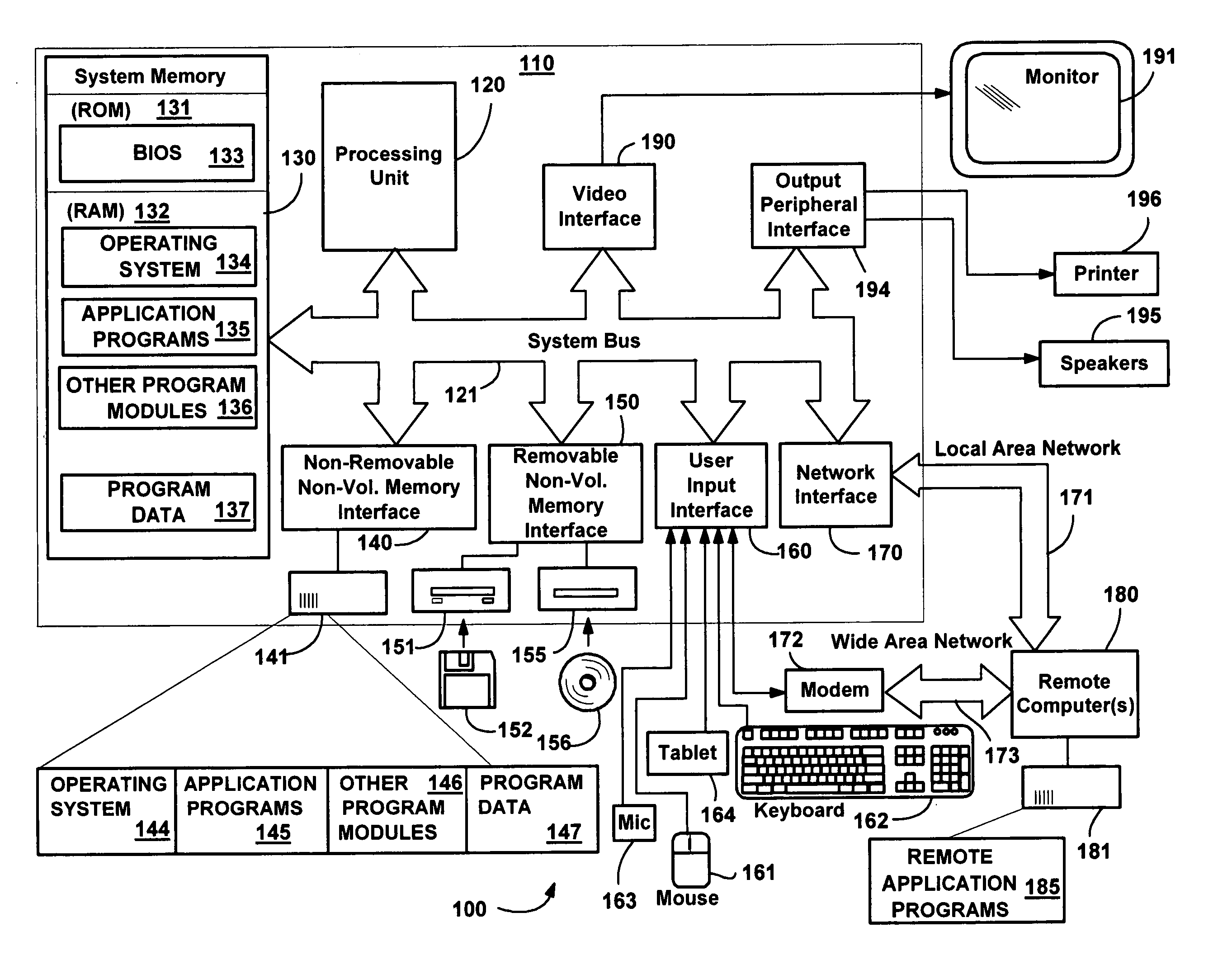
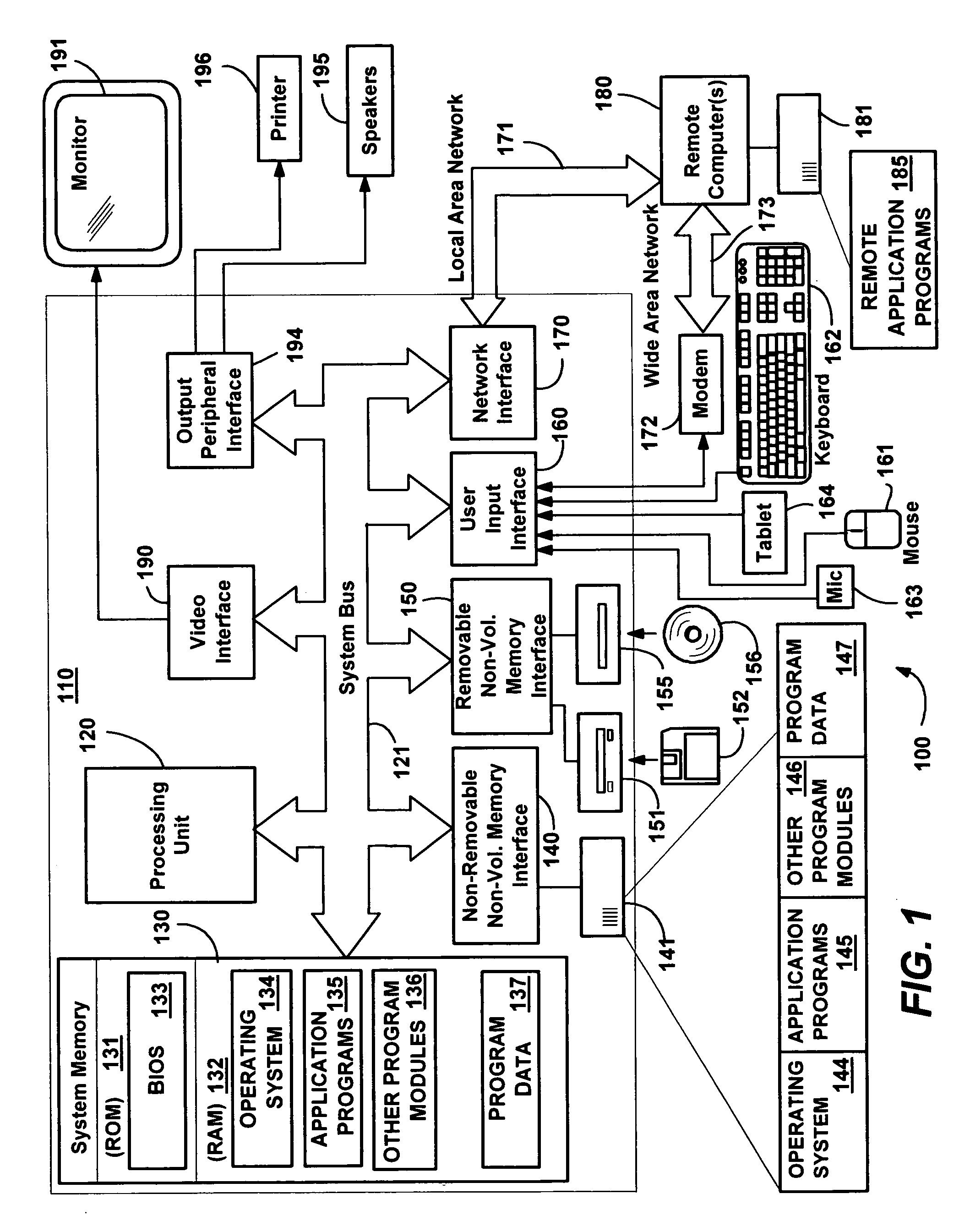
[0030]FIG. 1 illustrates an example of a suitable computing system environment 100 on which the invention may be implemented. The computing system environment 100 is only one example of a suitable computing environment and is not intended to suggest any limitation as to the scope of use or functionality of the invention. Neither should the computing environment 100 be interpreted as having any dependency or requirement relating to any one or combination of components illustrated in the exemplary operating environment 100.

[0031] The invention is operational with numerous other general purpose or special purpose computing system environments or configurations. Examples of well known computing systems, environments, and / or configurations that may be suitable for use with the invention include, but are not limited to: personal computers, server computers, hand-held or laptop devices, tablet devices, multiprocessor systems, microprocessor-based systems, ...


PUM


Abstract

Described is a protocol by which wireless network communication devices comprising peer nodes (such as a computer system and an access point) cooperatively exchange information about RF interference detected in the network. The protocol administers the exchange of formatted control data corresponding to the detected interference among computing nodes running a service capable of processing the control data. A peer table is used to maintain locally-obtained and remotely-obtained control data. Records in the peer table are arranged with different levels of granularity with respect to interference and networking information. The interference information collected through the cooperative protocol may then be used by peer devices in the network to adapt to mitigate interference-related problems. The protocol also provides for discovery of peer node capabilities, including a negotiable transport for the control data that may be different from the main data channel transport.

Description

CROSS-REFERENCE TO RELATED APPLICATIONS [0001] The present invention is related to the following copending U.S. patent applications filed concurrently herewith, assigned to the assignee of the present invention, and hereby incorporated by reference in their entireties: [0002]“Extensible Framework for Mitigating Interference Problems in Wireless Networking,” U.S. patent application Ser. No. ______; and [0003]“Use of Separate Control Channel to Mitigate Interference Problems in Wireless Networking,” U.S. patent application Ser. No. ______.FIELD OF THE INVENTION [0004] The invention relates generally to computer systems, and more particularly to exchanging information in wireless networks. BACKGROUND [0005] Wireless local area networks (WLANs) are proliferating in both home and enterprises. Such wireless networks may be used for web browsing, file transferring, audiovisual streaming, sending and receiving messages, and other purposes. As wireless connectivity spreads, the likelihood of...

Claims


Application Information

Patent Timeline
IPC IPC(8): H04L12/28H04W24/00
CPCH04W24/00H04B1/10H04B15/00H04B15/02H04L12/28
Inventor PONCINI, VICTORIA M.MADHAVAN, POOVANPILLI G.ABHISHEK, ABHISHEK
Owner MICROSOFT TECH LICENSING LLC
Why Eureka
Try Eureka