Hydraulic pressurizer system

a hydraulic pressurizer and hydraulic technology, applied in the direction of positive displacement liquid engines, fluid couplings, hybrid vehicles, etc., can solve the problems of limited idling-elimination effectiveness, inefficient performance of hydraulic pressurizer systems in idling-elimination, and inability to achieve appropriate hydraulic pressure by electrical oil pumps. achieve cost-effective

a hydraulic pressurizer and hydraulic technology, applied in the direction of positive displacement liquid engines, fluid couplings, hybrid vehicles, etc., can solve the problems of limited idling-elimination effectiveness, inefficient performance of hydraulic pressurizer systems in idling-elimination, and inability to achieve appropriate hydraulic pressure by electrical oil pumps. achieve cost-effective

US20060120876A1Inactive Publication Date: 2006-06-08HONDA MOTOR CO LTD +1

Image

  • Hydraulic pressurizer system
  • Hydraulic pressurizer system
  • Hydraulic pressurizer system

Examples


Embodiment Construction

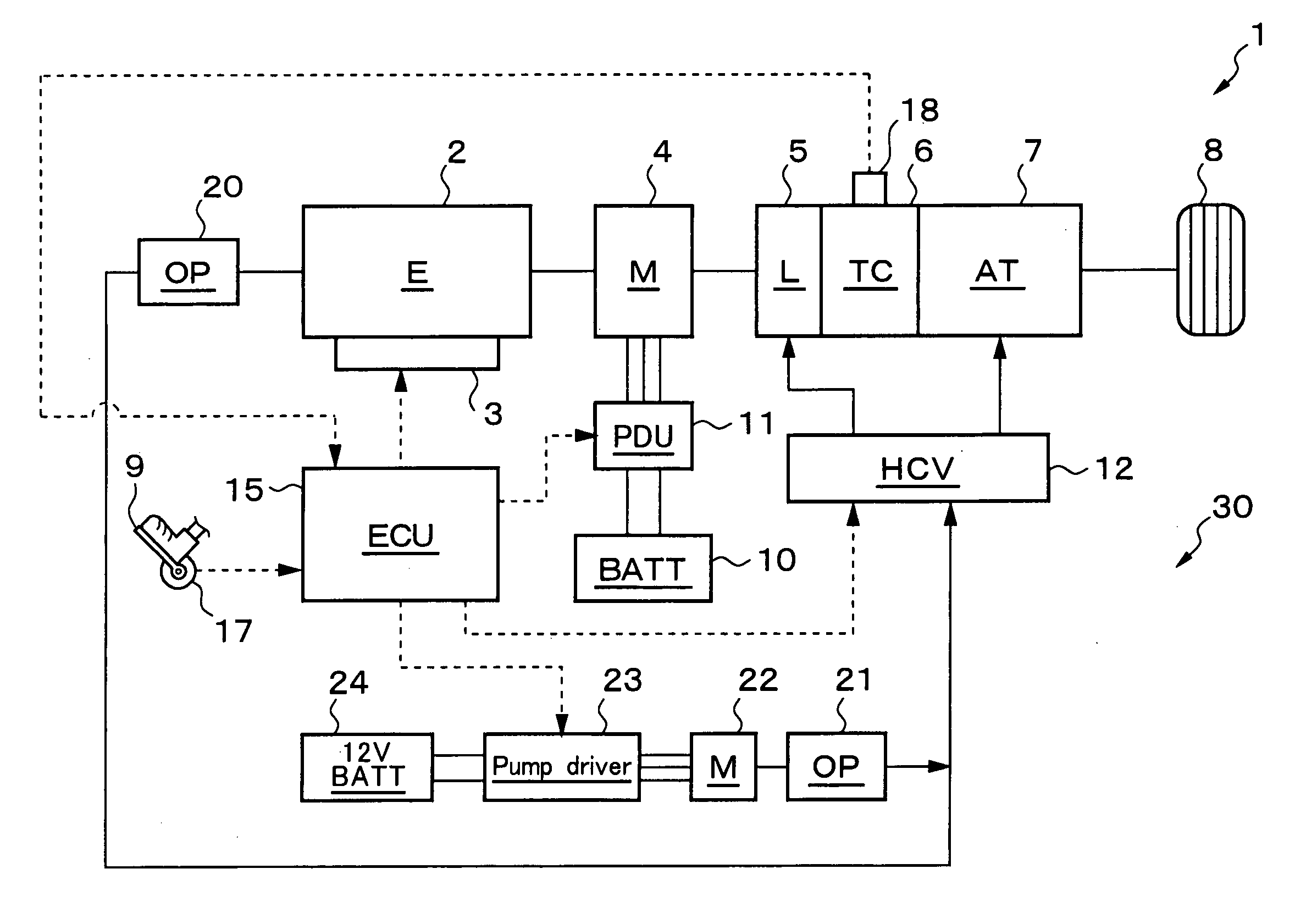
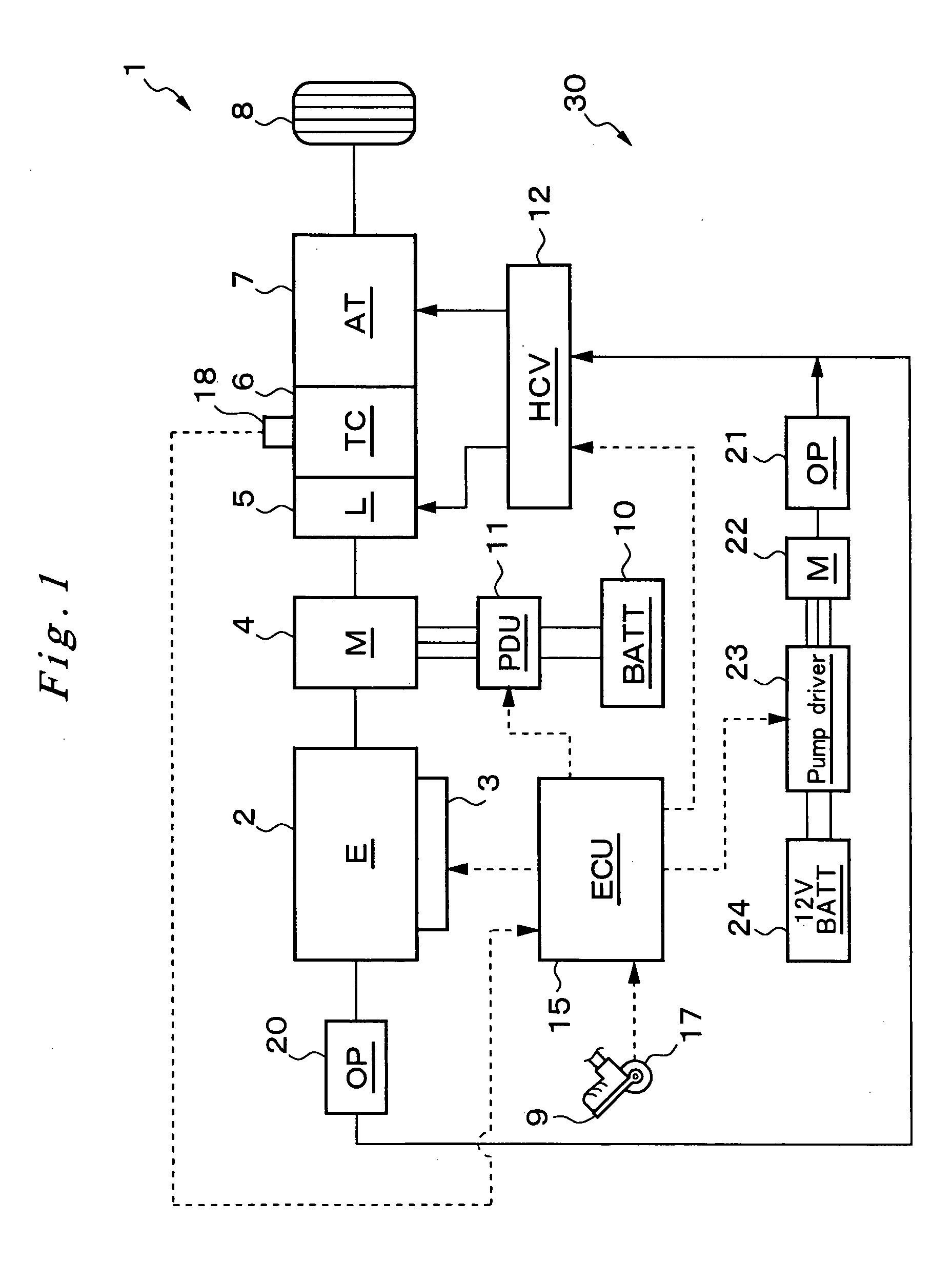
[0025] Now, preferred embodiments according to the present invention are described in reference to the drawings. At first, the construction of the drive system of a hybrid vehicle, which is equipped with a hydraulic pressurizer system according to the present invention, is described in reference to FIG. 1.

[0026] This hybrid vehicle 1 comprises an engine 2 and an electricity-generating motor (referred to as motor generator) 4 as drive sources, which are connected in series. The vehicle also comprises a torque converter 6, which is connected to the drive sources and equipped with a lock-up clutch 5, and an automatic ratio-change mechanism 7, whose output shaft is connected to drive wheels 8. In this arrangement, the driving force applied alternatively from the engine 2 or the motor generator 4 or simultaneously from these two is transmitted through the torque converter 6 with the lock-up clutch 5 and the automatic ratio-change mechanism 7 to the wheels 8, driving the hybrid vehicle 1...


PUM


Abstract

A hydraulic pressurizer system 30 comprises a drive source (an engine 2 and a motor generator 4), which drives a hybrid vehicle 1, a mechanical oil pump 20, which is driven by the drive source, an electrical motor 22, which is activated by a 12V battery 24, an electrical oil pump 21, which is driven by the electrical motor 22, and a control unit 15, which activates the electrical motor 22. The pressurizer further comprises a ratio-change mechanism 7, which is activated by hydraulic oil supplied by the mechanical oil pump 20 and by the electrical oil pump 21 to establish a speed change ratio, at which the rotational driving force of the drive source is transmitted to wheels 8 with a rotational speed change. The control unit 15 memorizes a characteristic value CV, which is specified from the temperature of the hydraulic oil and from the rotational speed of the electrical motor 22, and a threshold value NTH2 for the rotational speed Np of the electrical motor 22, which threshold value corresponds to the characteristic value CV. While the control unit 15 is executing a so-called idling-stop control, it cancels the idling-stop control if the rotational speed Np of the electrical motor 22 reaches the threshold value NTH2.

Description

FIELD OF THE INVENTION [0001] The present invention relates to a hydraulic pressurizer system, which is used, for example, in a hybrid vehicle and which supplies hydraulic oil to the ratio-change mechanism and the like by an electrically driven oil pump while the engine is not in operation. BACKGROUND OF THE INVENTION [0002] A hybrid vehicle is driven by a drive source that is a combination of an engine and a motor capable of electricity generation (motor generator), and such a vehicle has been developed for improving fuel efficiency and for reducing exhaust gas in environmental protection. Typically, a hybrid vehicle is controlled for stopping the engine when the vehicle stops in so-called idling-elimination. In this case, when the engine stops, the mechanically driven oil pump, which has been in operation for supplying hydraulic oil, for example, to the ratio-change mechanism, also stops. Therefore, for complementarity, an electrically driven oil pump or electrical oil pump is pro...

Claims


Application Information

Patent Timeline
08 Jun 2006
Publication
US20060120876A1
IPC
F04B49/00; B60W10/10; F02D29/02; F16H59/50; F16H59/68; F16H59/72; F16H61/00; F16H61/02
CPC
B60K6/48; F16H61/0025; F16H61/0031; Y02T10/6221; Y02T10/62
Inventors
KITANO, KAZUHIKO; MIYAMOTO, OSAHIDE