Posterior lumbar interbody fusion expandable cage with lordosis and method of deploying the same

a lordosis and expandable cage technology, applied in the field of posterior lumbar fusion cages, can solve the problems of all the standard approaches, neural injury, nerve damage and potential neurologic deficit,

Inactive Publication Date: 2006-06-08
RGT UNIV OF CALIFORNIA
View PDF5 Cites 611 Cited by
  • Summary
  • Abstract
  • Description
  • Claims
  • Application Information

AI Technical Summary

Problems solved by technology

There are problems with all of the standard approaches.
If the retraction is not done properly, the procedure could cause neural injury, i.e., nerve damage and potential neurologic deficit.
Violation of the great vessels has a high mortality rate.
The device disclosed in the Larsen reference has several problems.
One problem is that, because the width of the implant is adjusted prior to insertion, a wide insertion slot is necessary despite the reduced profile presented by the collapsed implant.
Another problem is that at least part of the linkage mechanism extends beyond the upper and lower plate portions, thus requiring more invasion into the body cavity to position the implant.
Yet another problem is that the linkage mechanisms must be locked into the expanded position by conventional arrangements such as locking screws.
Brett, U.S. Pat. No. 6,126,689 (2000), illustrates an expandable and collapsible fusion cage, but it design is extremely complex and therefore expensive to manufacture and prone to failure in the field.
Moreover, its complex linkages require special surgical skills in its deployment.
Indeed, there is no reliable deployment mechanism.
The Brett design requires large hinges which make it too large and therefore unsuitable for posterior insertion.
Second, there is a large surface area to fuse.
Indeed, it is the low but real incidence of major complications associated with the anterior surgical approach which is largely responsible for the decreasing popularity of anteriorly placed cylindrical cages.
Kiester, U.S. Pat. No. 6,893,464 (2005) provided for an improved design, but incorporated a design which was not as strong or rugged as might be desired in some applications.
The prior art designs for posterior lumbar interbody fusion expandable cages all suffer from the common defect that they interfere with spinal fusion.

Method used


Image

  • Posterior lumbar interbody fusion expandable cage with lordosis and method of deploying the same
  • Posterior lumbar interbody fusion expandable cage with lordosis and method of deploying the same
  • Posterior lumbar interbody fusion expandable cage with lordosis and method of deploying the same

Examples


Embodiment Construction

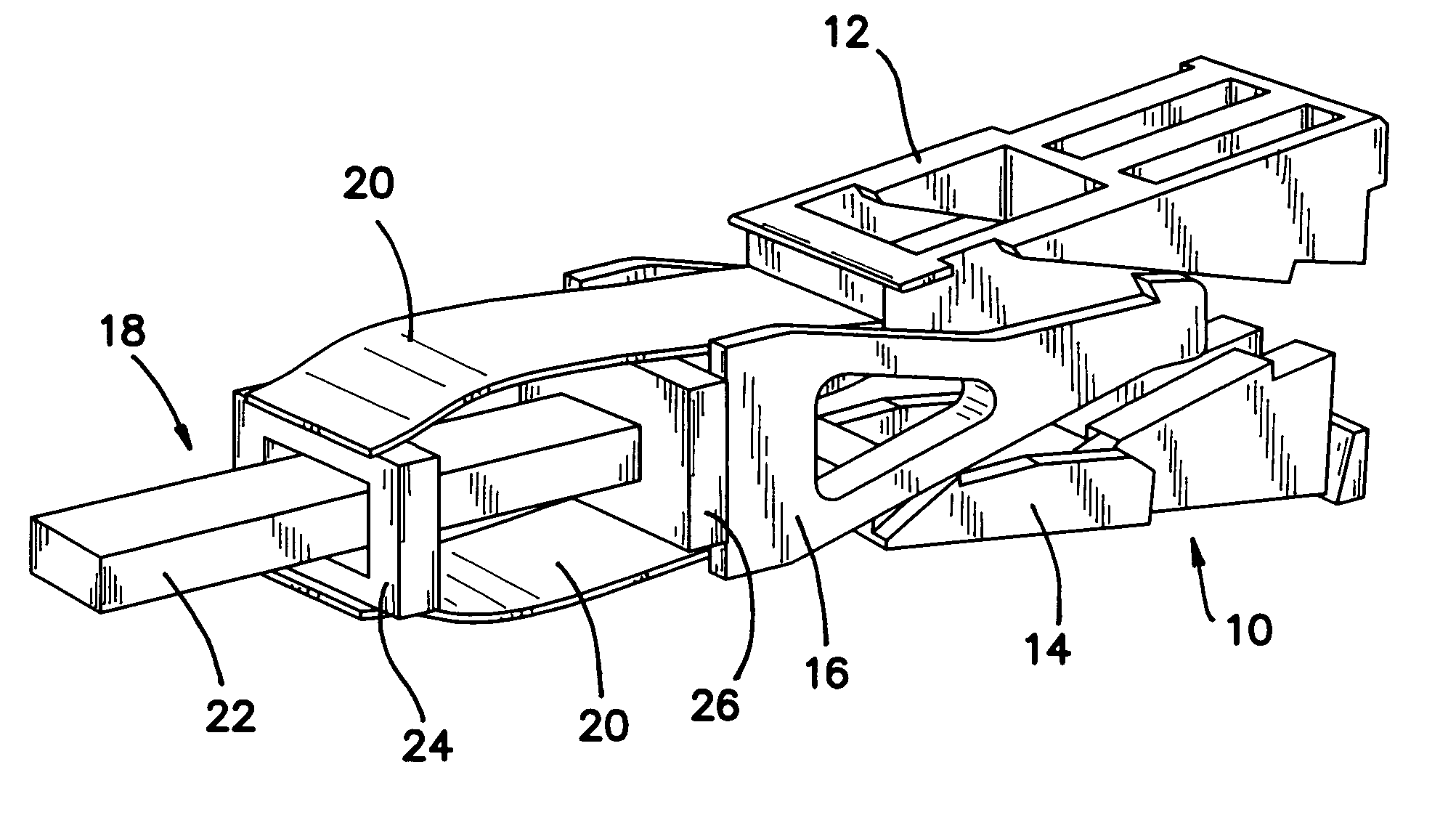
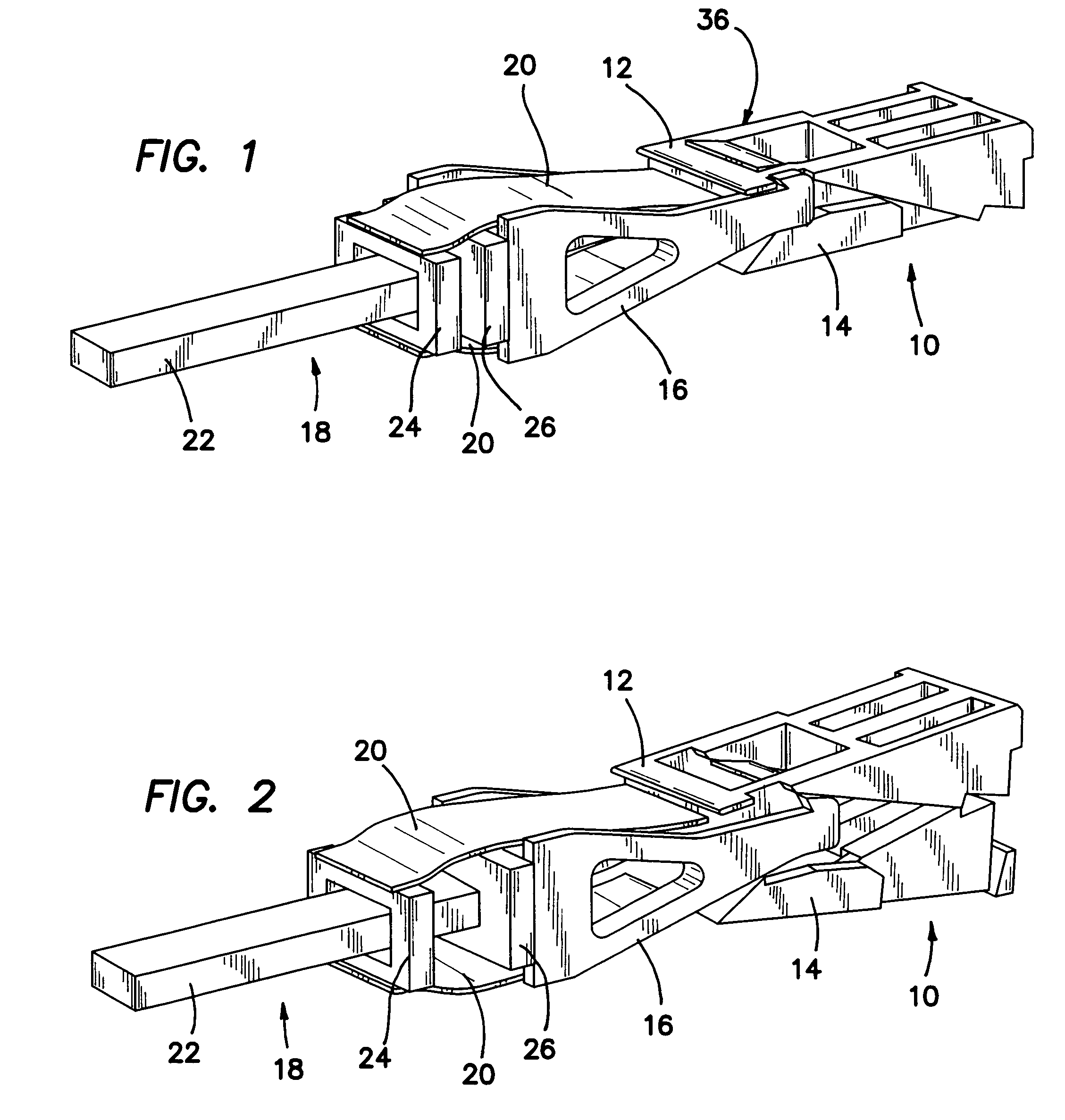
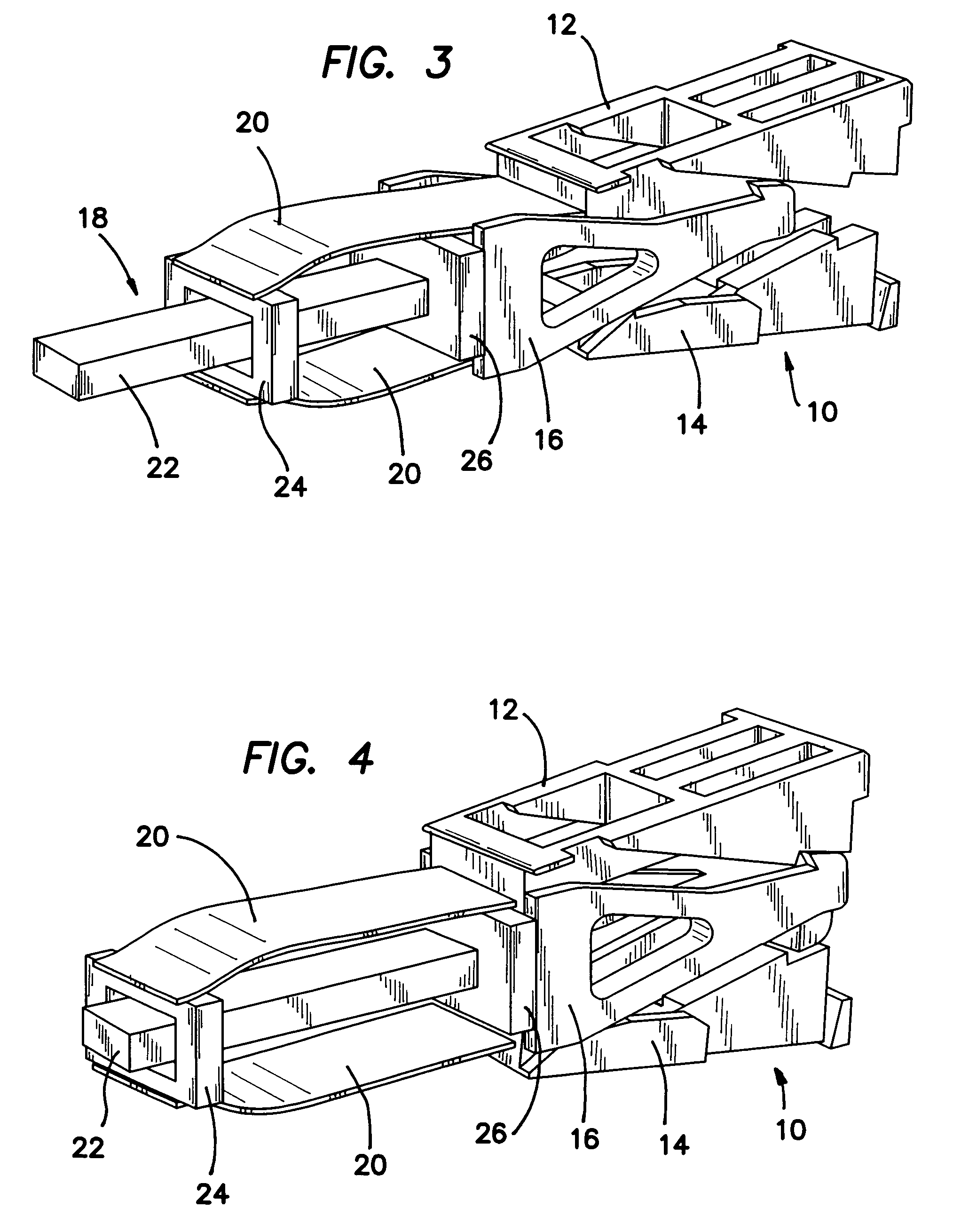
[0060] The spinal fusion cage 10 as best shown in assembled perspective view of FIG. 5 is comprised of two half-cages 12 and 14 and a middle plunger 16 which is slid between the half-cages 12 and 14 by means of a removable pusher tool 18. It should be borne in mind that during the sequence of steps illustrated in FIGS. 1-6 that half-cages 12 and 14 will be inserted into the spinal column between two adjacent vertebrae and hence will tend to pushed together by the vertebrae. The assembly of fusion cage 10 is then done against the opposing force of the adjacent vertebrae, which will be fused together in a predetermined position with a predetermined relative angle between them as provided by the invention.

[0061] Turning first to the unassembled perspective view of FIG. 1 we see that the pusher tool 18 is coupled to the plunger 16 by two opposing leaf springs 20 that clasp opposing top and bottom sides of the plunger 16 and slide off the plunger 16 as it is forced between the two half-...


PUM


Abstract

A spinal fusion cage comprises an upper half-cage, a lower half-cage, and a plunger with a cam. The upper half-cage and lower half-cage have a first collapsed configuration which has a thin, flat, rectangular envelope and a second expanded configuration. The half-cages have at least one ramped surface on which the cam of the plunger rides. The cam bears against the ramped surface and spreading the two half-cages apart. A method of deploying a spinal fusion cage comprises the steps of disposing in a spinal space an upper half-cage and lower half-cage in a first collapsed configuration which has a thin, flat, rectangular envelope and a second expanded configuration. The method continues with the step of distally advancing a plunger between the upper half-cage and lower half-cage and spreading the two half-cages apart.

Description

RELATED APPLICATIONS [0001] The present application is related to U.S. Provisional Patent Application serial No. 60 / 630,944, filed on Nov. 23, 2004 and U.S. Provisional Patent Application serial No. 60 / 680,264, filed on May 11, 2005, which are incorporated herein by reference and to which priority is claimed pursuant to 35 USC 119.BACKGROUND OF THE INVENTION [0002] 1. Field of the Invention [0003] The invention relates to the field of implantable fusion cages for use in the spinal column. [0004] 2. Description of the Prior Art [0005] Fusion cages provide a space for inserting a bone graft between adjacent portions of bone. In time, the bone and bone graft grow together through or around the fusion cage to fuse the graft and the bone solidly together. One current use of fusion cages is to treat a variety of spinal disorders, including degenerative disc diseases, Grade I or II spondylolistheses, adult coliosis and other disorders of the lumbar spine. Spinal fusion cages (included in t...

Claims


Application Information

Patent Timeline
Patent Type & Authority Applications(United States)
IPC IPC(8): A61F2/44A61B17/88
CPCA61F2/447A61F2/4611A61F2002/30266A61F2002/30383A61F2002/30476A61F2002/3052A61F2002/3055A61F2002/30556A61F2002/30784A61F2002/30975A61F2002/4627A61F2220/0025A61F2230/0082A61F2250/0009
Inventor KIESTER, P. DOUGLAS
Owner RGT UNIV OF CALIFORNIA
Why Eureka
Try Eureka