Control device and system for controlling an actuated prosthesis

Active Publication Date: 2006-06-08
NATIONAL BANK OF CANADA
View PDF39 Cites 99 Cited by
  • Summary
  • Abstract
  • Description
  • Claims
  • Application Information

AI Technical Summary

Benefits of technology

[0046] means for converting the dynamic parameter value

Problems solved by technology

As is well known to control engineers, the automation of complex mechanical systems is not something easy to achieve.
Among such systems, conventional powered artificial limbs, or myoelectric prostheses, as they are more commonly referred to, are notorious for having control problems.
These conventional prostheses are equipped with basic controllers that artificially mobilize the joints without any interaction from the amputee and are only capable of generating basic motions.
Such basic controllers do not take into consideration the dynamic conditions of the working environment, regardless of the fact that the prosthesis is required to generate appropriate control within a practical application.
They are generally lacking in predictive control strategies necessary to anticipate the artificial limb's response as well as lacking in adaptive regulation enabling the adjustment of the control parameters to the dynamics of the prosthesis.
Because human limb mobility is a complex process including voluntary, reflex and random events at the same time, conventional myoelectric prostheses do not have the capability to interact simultaneously with the human body and the external environment in order to have minimal appropriate functioning.
This proved to be truly detrimental to the integration

Method used


Image

  • Control device and system for controlling an actuated prosthesis
  • Control device and system for controlling an actuated prosthesis
  • Control device and system for controlling an actuated prosthesis

Examples


Embodiment Construction

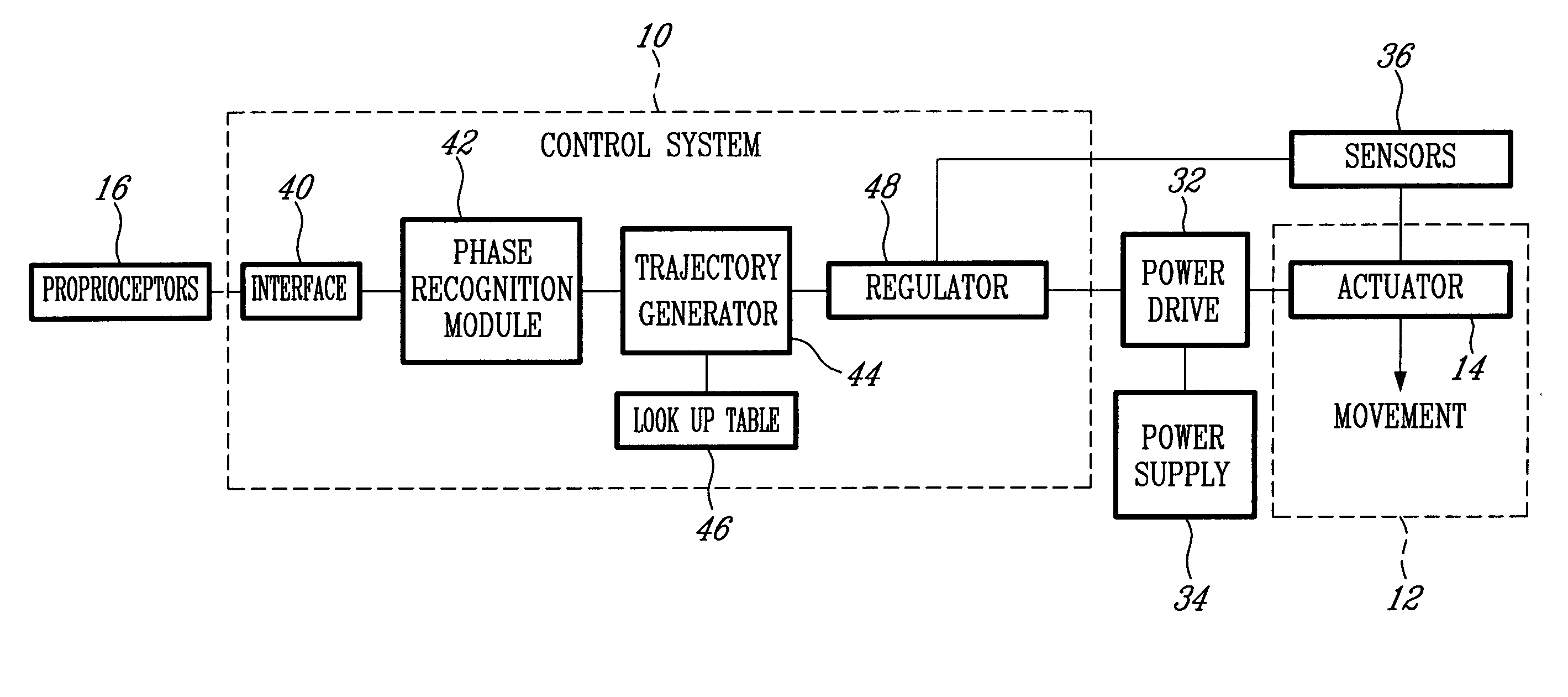
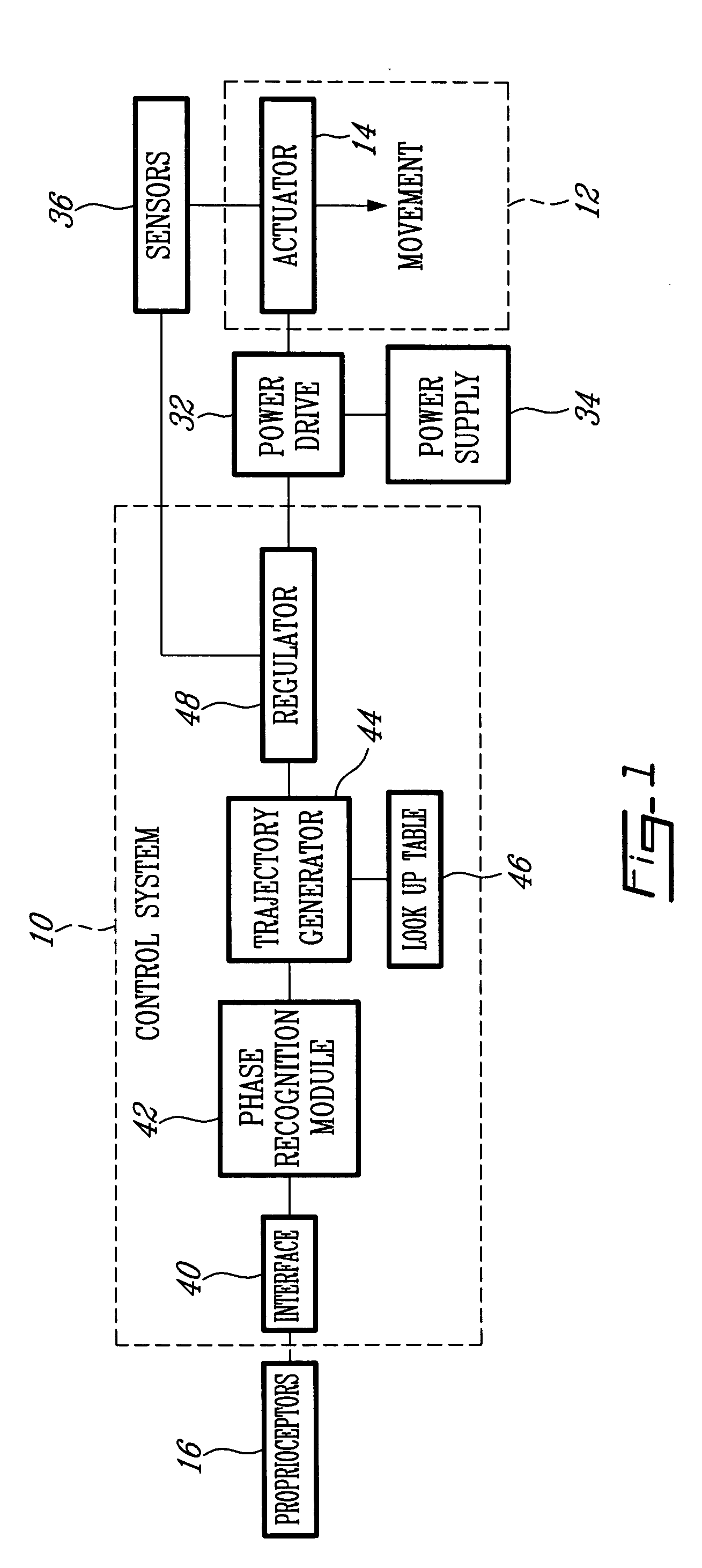
[0070] The appended figures show a control system (10) in accordance with the preferred embodiment of the present invention. It should be understood that the present invention is not limited to the illustrated implementation since various changes and modifications may be effected herein without departing from the scope of the appended claims.

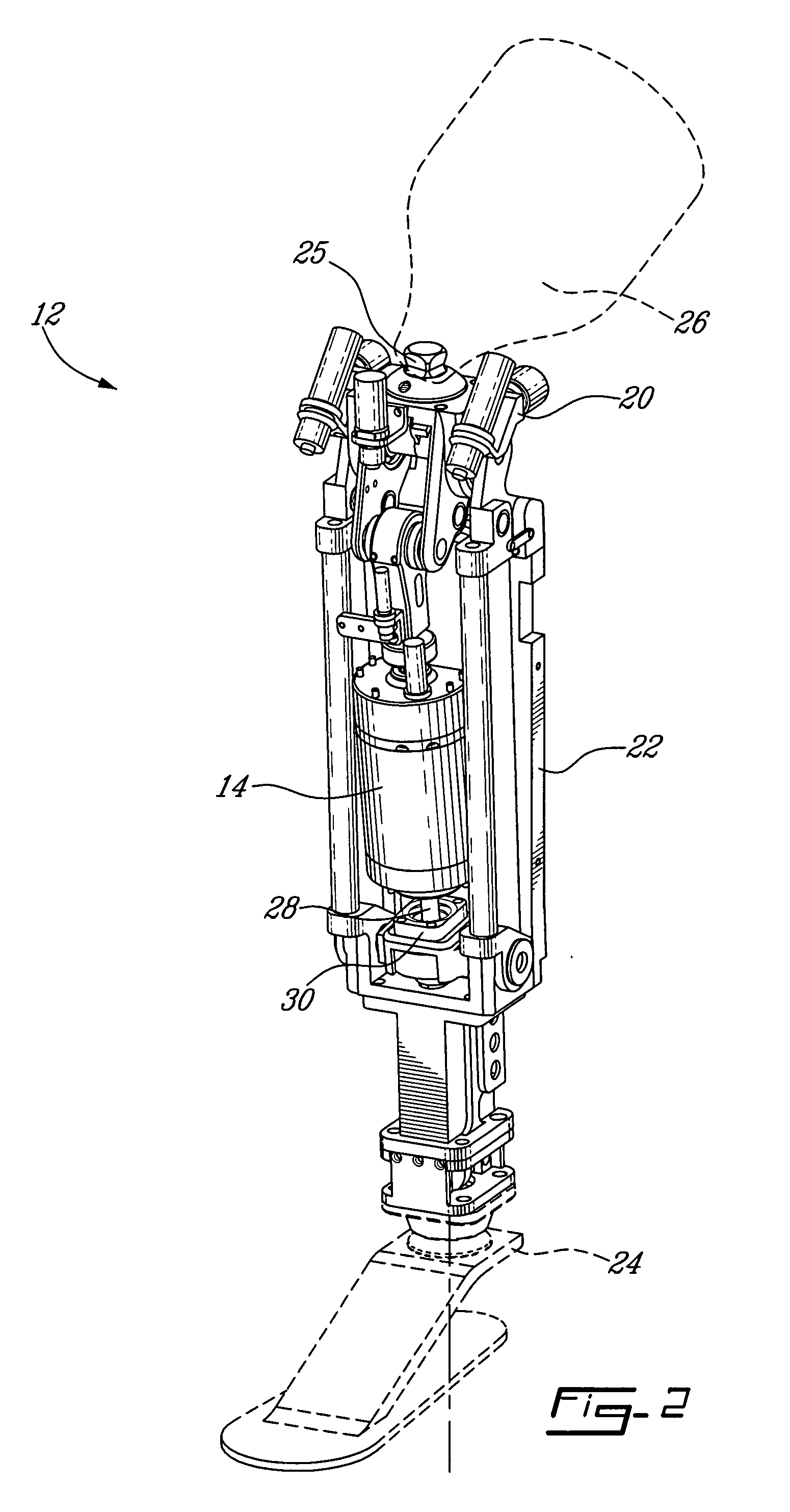
[0071]FIG. 1 shows the control system (10) being combined with an autonomous actuated prosthesis for amputees. It is particularly well adapted for use with an actuated leg prosthesis for above-knee amputees, such as the prostheses (12) shown in FIGS. 2 and 3. Unlike conventional prostheses, these autonomous actuated prostheses (12) are designed to supply the mechanical energy necessary to move them by themselves. The purpose of the control system (10) is to provide the required signals allowing to control an actuator (14). To do so, the control system (10) is interfaced with the amputee using artificial proprioceptors (16) to ensure proper coor...


PUM


Abstract

A device and system for controlling an actuated prosthesis. The device includes a data signal input for each of the main artificial proprioceptors. Also, means for obtaining a first and a second derivative signal for at least some of the data signals, and means for obtaining a third derivative signal for at least one of the data signals. A set of first state machines, and means for generating the phase of locomotion portion using the states of the main artificial proprioceptors, and a second state machine as also included. The system includes a plurality of main artificial proprioceptors as well as means for obtaining a first and a second derivative signal for at least some of the data signals, and means for obtaining a third derivative signal for at least one of the data signals. Also, a set of first state machines, a second state machine, means for storing a lookup table, means for determining actual coefficient values from the lookup table, means for calculating at least one dynamic parameter value of the actuated prosthesis using the lookup table and at least some of the data signals, and means for converting the dynamic parameter value into an output signal to control the actuated prosthesis.

Description

CROSS-REFERENCE TO RELATED APPLICATIONS [0001] The present application is a divisional of Ser. No. 10 / 600,725 filed Jun. 20, 2003 which claims the benefit of U.S. provisional patent applications No. 60 / 405,281 filed Aug. 22, 2002; No. 60 / 424,261 filed Nov. 6, 2002; and No. 60 / 453,556 filed Mar. 11, 2003, all of which are hereby incorporated by reference.TECHNICAL FIELD [0002] The present invention relates to a control system and a method for controlling an actuated prosthesis. This invention is particularly well adapted for controlling an actuated leg prosthesis for above-knee amputees. BACKGROUND OF THE INVENTION [0003] As is well known to control engineers, the automation of complex mechanical systems is not something easy to achieve. Among such systems, conventional powered artificial limbs, or myoelectric prostheses, as they are more commonly referred to, are notorious for having control problems. These conventional prostheses are equipped with basic controllers that artificiall...

Claims


Application Information

Patent Timeline
IPC IPC(8): A61F2/70A61F2/64A61F2/60A61F2/66A61F2/68A61F2/76
CPCA61F2/644A61F2/68A61F2002/607A61F2002/6614A61F2002/701A61F2002/704A61F2002/705A61F2002/762A61F2002/7625A61F2002/7635A61F2002/7685A61F2/6607A61F2/70A61F2002/763A61F2002/7645
Inventor BEDARD, STEPHANE
Owner NATIONAL BANK OF CANADA
Why Eureka
Try Eureka