Marine engine fuel cooling system

a technology for marine engines and cooling systems, which is applied in the direction of machines/engines, combustion air/fuel air treatment, lighting and heating apparatus, etc., and can solve the problems of increasing the temperature of the fuel in the tank, reducing engine efficiency, and reducing power

Inactive Publication Date: 2006-06-15
ROBERTS FOREST G SR
View PDF25 Cites 201 Cited by
  • Summary
  • Abstract
  • Description
  • Claims
  • Application Information

AI Technical Summary

Problems solved by technology

A problem arises with constant fuel re-circulation systems because the heat emitted by the diesel engine is transferred to the re-circulated fuel returning to the fuel tank, thus raising the temperature of the fuel in the

Method used


Image

  • Marine engine fuel cooling system
  • Marine engine fuel cooling system
  • Marine engine fuel cooling system

Examples


Embodiment Construction

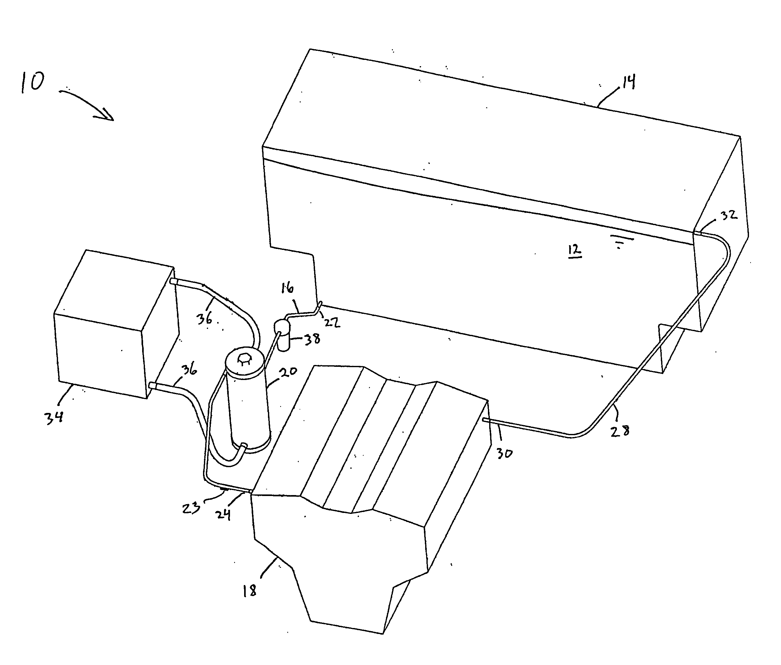
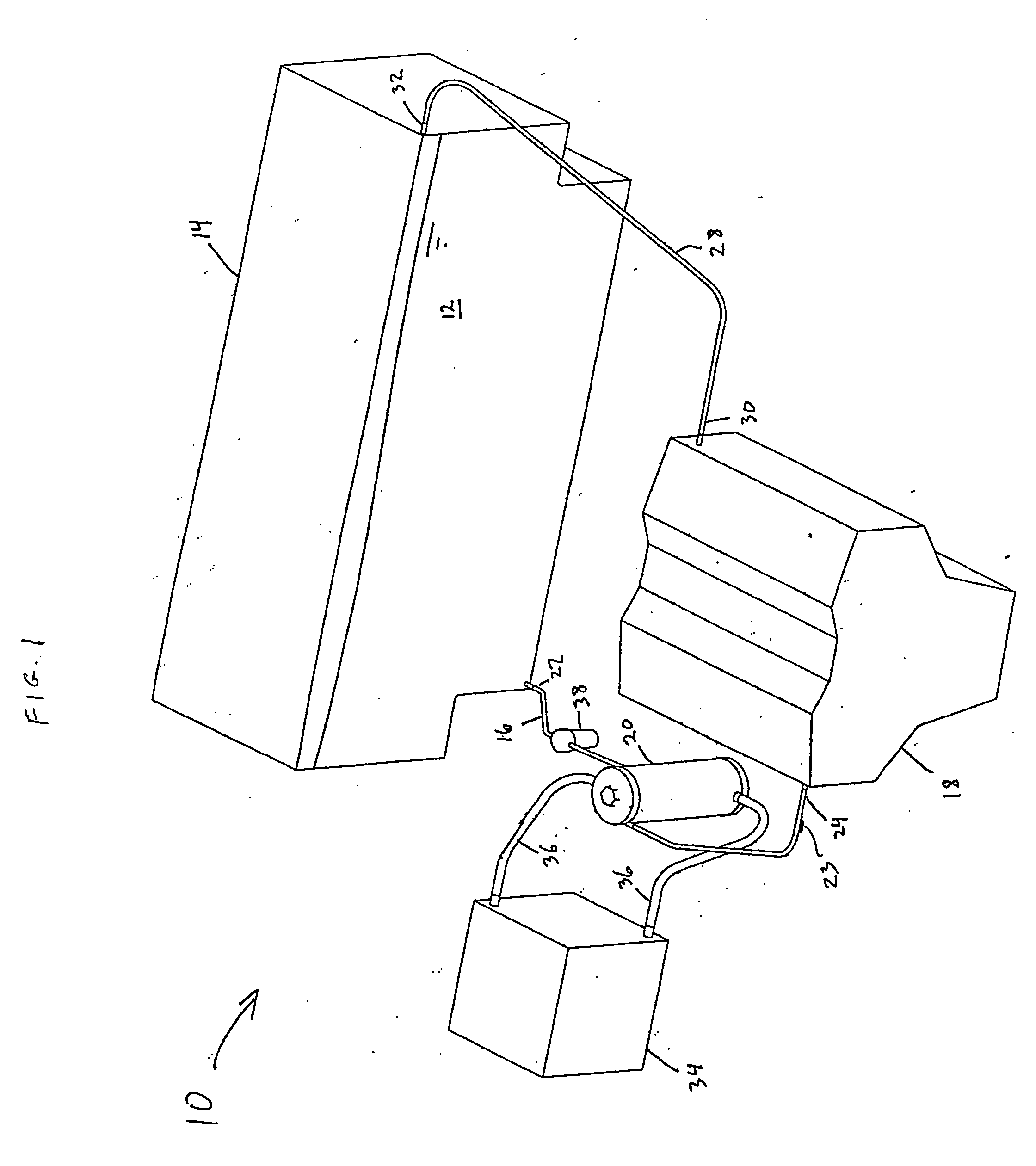
[0012]FIG. 1 schematically illustrates one embodiment of a fuel cooling system 10 for a marine inboard engine. In the embodiment, diesel fuel 12 is contained under atmospheric pressure in a fuel tank 14 that is typically disposed remote from a marine diesel inboard engine 18. A fuel supply conduit 16 may be connected to a lower portion of the fuel tank 14 at a first end 22, and is subject to the head pressure of the fuel 12 in the tank 14. A second end 24 of the fuel supply conduit 16 is in fluid communication with a fuel injector system (not shown) which may be mounted on the marine inboard diesel engine 18. A temperature sensor 23 may be disposed at second end 24 of the fuel supply conduit 16 for monitoring the temperature of the fuel 12 flowing through the fuel injector system. The fuel injector system includes a fuel pump (not shown). A fuel return conduit 28 is in fluid communication with a terminal portion of the fuel injector system at a first end 30, and is connected to an u...


PUM


Abstract

A fuel cooling system for a marine inboard engine, including a fuel tank, a fuel supply conduit, and a heat exchanger. The fuel supply conduit includes first and second ends, and extends between the fuel tank and a fuel injection system for the engine. The heat exchanger is disposed intermediate the first and second ends of the fuel supply conduit, and includes a fuel passage in fluid communication with the fuel supply conduit, and a coolant passage in fluid communication with a coolant side of a closed-loop auxiliary cooling system.

Description

FIELD OF THE INVENTION [0001] This invention relates generally to a fuel cooling system for an internal combustion engine, and more particularly to a fuel cooling system for a marine diesel inboard engine. BACKGROUND OF THE INVENTION [0002] Fuel delivery systems for marine inboard diesel engines include a fuel tank, a fuel supply conduit, a fuel injection system including a fuel pump, and a fuel return conduit. Diesel fuel is supplied from the tank, through the supply conduit, and to the fuel injection system. Fuel is then injected into combustion cylinders of the diesel engine, mixed with air, and combusted. The fuel injection system requires a continuously circulating supply of fuel, whereby excess fuel that is not injected into the combustion cylinders is returned to the fuel tank via the fuel return conduit. This process is known as constant fuel re-circulation. A problem arises with constant fuel re-circulation systems because the heat emitted by the diesel engine is transferre...

Claims


Application Information

Patent Timeline
IPC IPC(8): F02M31/20
CPCF02M31/20F28D7/024Y02T10/126Y02T10/12
Inventor ROBERTS, FOREST G. SR.
Owner ROBERTS FOREST G SR
Why Eureka
Try Eureka