Heat exchanger and method of manufacture thereof

a technology of heat exchanger and heat sealing section, which is applied in the direction of heat exchanger types, lighting and heating apparatus, laminated elements, etc., can solve the problems of heat sealing section separation, and achieve good heat transmission

Inactive Publication Date: 2006-06-15
OXYCOM BEHEER BV
View PDF35 Cites 51 Cited by
  • Summary
  • Abstract
  • Description
  • Claims
  • Application Information

AI Technical Summary

Benefits of technology

[0009] According to the present invention there is provided a heat exchange element comprising a formable laminate of a metal layer and a heat-seal layer, the laminate being sealed under heat and pressure to itself or to another similar laminate to form a flow channel for a heat exchange medium. By providing such a formable laminate, complex shapes such as convolutions, fins and the like may be easily produced that are fluid tight, ensure good heat transmission and are robust.

Problems solved by technology

In particular, by choosing a material that is relatively inelastic, deformation of the laminate is unlikely to cause separation of the heat-sealed sections.

Method used


Image

  • Heat exchanger and method of manufacture thereof
  • Heat exchanger and method of manufacture thereof
  • Heat exchanger and method of manufacture thereof

Examples


Embodiment Construction

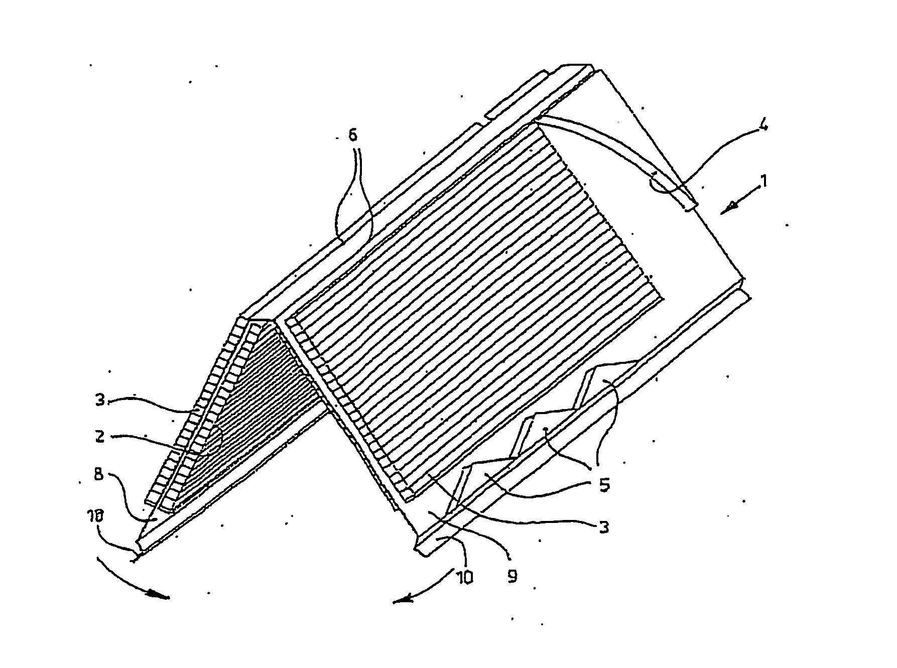
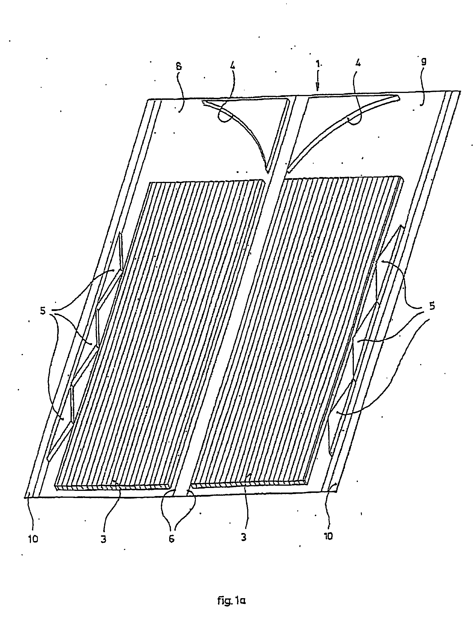
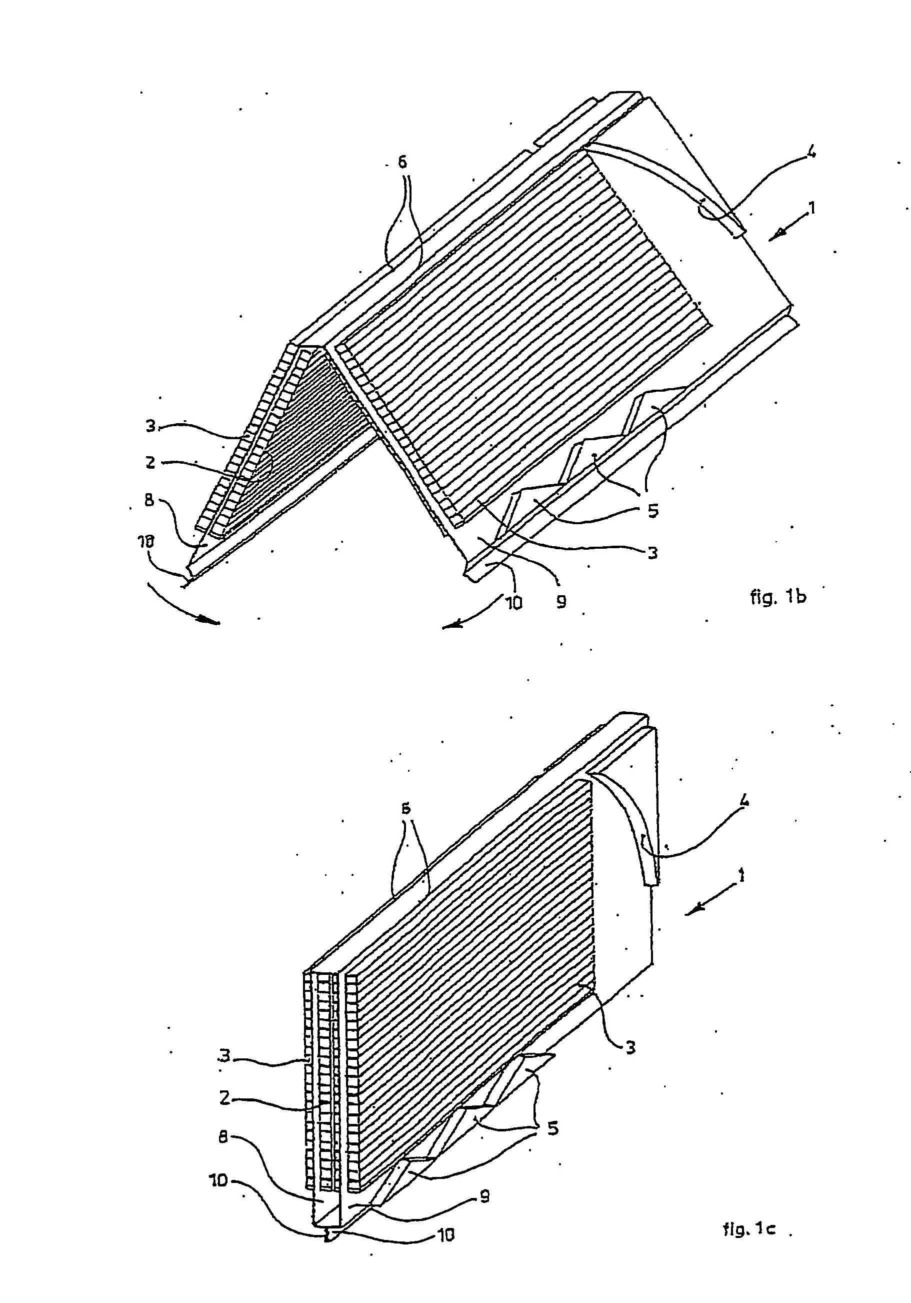
[0062]FIG. 1 shows a moulded sheet 1 consisting of a thin foil-like material of for instance polystyrene, PVC or PET. It is possible using such materials to apply a relatively small wall thickness, for instance in the order of 0.1 mm. Inexpensive production with a short throughput time is possible with for instance thermo-forming.

[0063] Sheet 1 is provided on both sides with schematically indicated packets of fins which, in FIG. 1, are designated 2 for the primary medium through-flow circuit and 3 for the secondary medium through-flow circuit.

[0064] Attention is drawn to the fact that the fins 2, 3 are shown very schematically. They consist in this embodiment of strips of limited length moulded in zigzag form in the longitudinal direction, i.e. the medium flow direction. This aspect is however not significant for the present invention.

[0065] Deflector dams 4 are formed in sheet 1 for deflecting the relevant medium flow. This aspect will be further elucidated with reference to FIG...


PUM

PropertyMeasurementUnit
thicknessaaaaaaaaaa
thicknessaaaaaaaaaa
thicknessaaaaaaaaaa

Abstract

Method of manufacturing a heat exchanger from a formable laminate (1, 11, 105) of a metal layer and a heat-seal layer whereby the laminate is sealed under heat and pressure to itself or to another similar laminate to form a flow channel for a heat exchange medium. Preferably the heat exchanger includes a series of fins (3, 106, 107) formed on the laminate (1, 11, 105) to increase heat transfer and may also include a water retaining layer (204).

Description

BACKGROUND OF THE INVENTION [0001] 1. Field of the Invention [0002] The present invention relates to a heat exchange element and a formable laminate for the manufacture of such a heat exchange element in particular for use in heat exchange between two fluid flows such as in an evaporative type heat exchanger. The invention also relates to a method of manufacturing such a heat exchange element. [0003] 2. Description of the Related Art [0004] Heat exchangers for heat exchange between two fluid streams are generally known in which a dividing wall separates the two fluid streams. In general, it is an objective of many such devices to increase the surface area of the dividing wall to increase the effective heat transfer between the two fluids. Generally, the wall will be thin to maximise the thermal gradient and in such cases, the conductivity of the wall material is not critical if its total area is sufficiently large. A device is known from EP0777094, which uses a corrugated sheet to p...

Claims


Application Information

Patent Timeline
Patent Type & Authority Applications(United States)
IPC IPC(8): F28F3/00F24F1/0035F24F5/00F28D9/00F28F3/02F28F3/06F28F17/00F28F21/06
CPCF24F5/0035F24F2001/0092F28D5/00F28D9/0025F28F3/027F28F2280/04F28F21/065F28F2245/02F28F2275/025Y02B30/545F28F2265/20F28F17/00F24F1/0007Y02B30/54F24F1/0035F28D9/00F28F3/02
Inventor REINDERS, JOHANNES ANTONIUS MARIA
Owner OXYCOM BEHEER BV
Why Eureka
Try Eureka