Magnetic heating device

a heating device and magnetic technology, applied in the field of magnetic heating devices, can solve the problems of heat loss of workpieces, metal heating, and same eddy current loss

Inactive Publication Date: 2006-06-15
MTECH HLDG
View PDF10 Cites 11 Cited by
  • Summary
  • Abstract
  • Description
  • Claims
  • Application Information

AI Technical Summary

Benefits of technology

[0014] According to a first group of embodiments the heating device is a separate unit adapted t...

Problems solved by technology

This induced current heats the metal because of resistive losses similar to any electrical resistance heating.
Magnetic flux passing through the workpiece induces flux lines to circulate in the plane of the strip and this res...

Method used


Image

  • Magnetic heating device
  • Magnetic heating device
  • Magnetic heating device

Examples


Embodiment Construction

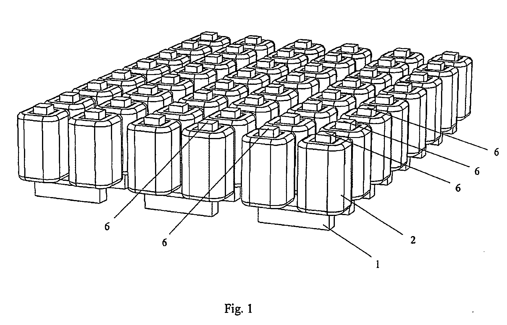
[0025] In FIG. 1 is shown a schematic illustration of a heating device including a number of magnetic modules. Each magnetic module includes two magnetic field generators.

[0026] Each magnet field generator includes a U-shaped magnetic core 1 provided with two magnetic coils 2. Each magnetic field generator has two free ends 6 (only some are indicated in the figure). In FIG. 1 is arranged three rows of magnetic modules with four modules in each row.

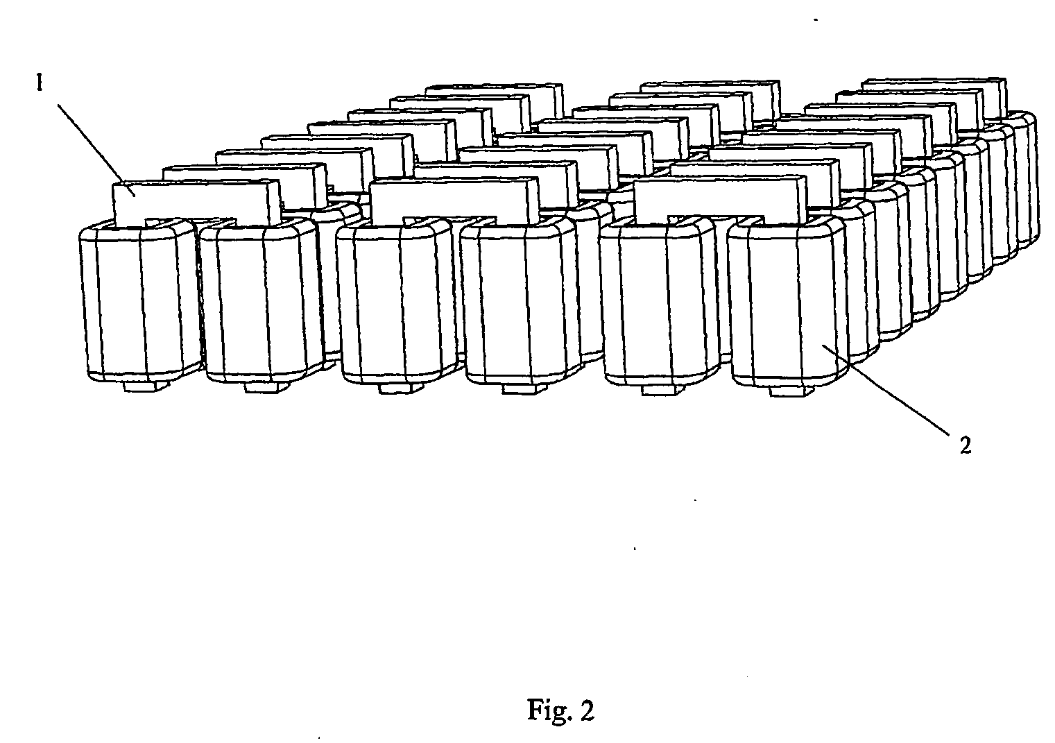
[0027]FIG. 2 shows, from below, a schematic illustration of a number of magnetic modules as shown in FIG. 1.

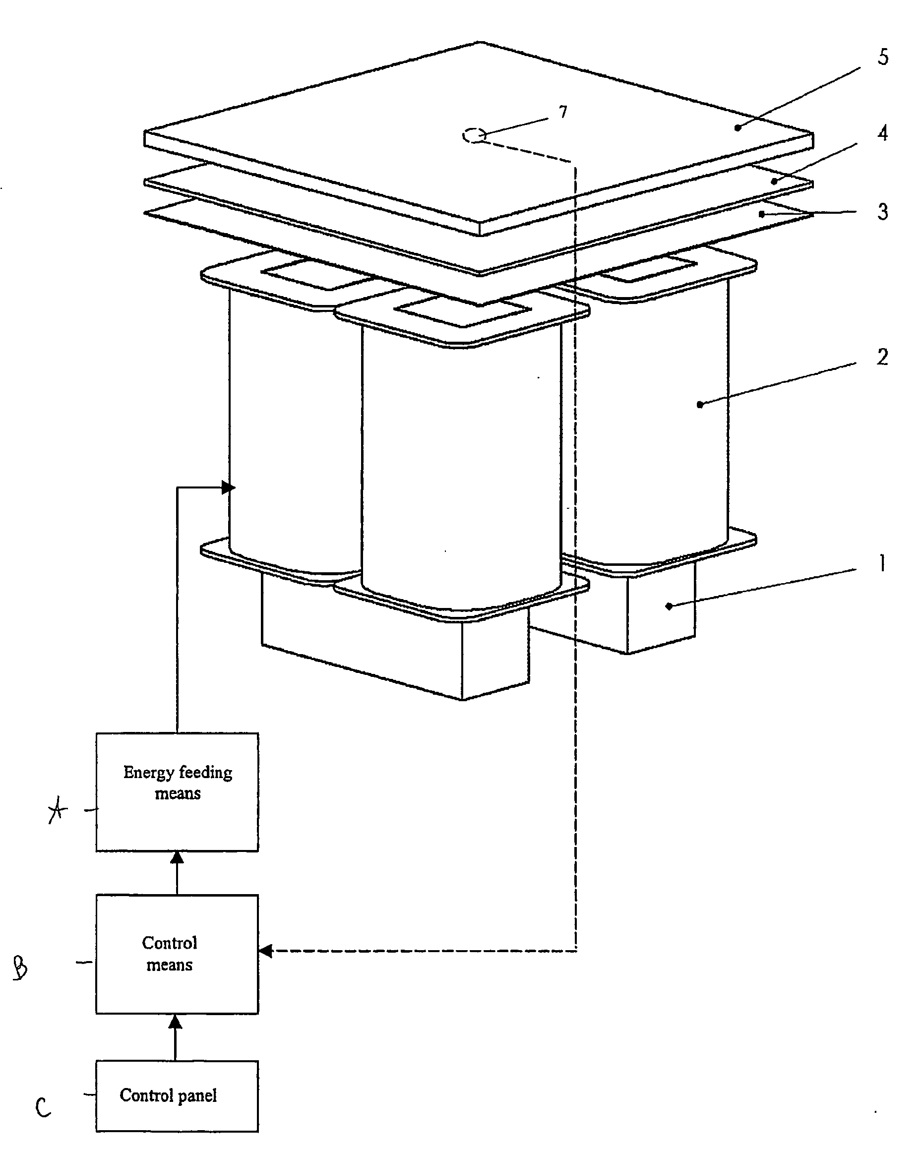
[0028]FIG. 3 shows a cross-sectional view and a view from above of one magnetic module according to present invention. In FIG. 3 is also included a heating means comprising a planar sheet that includes an upper ferromagnetic sheet 5 and a lower paramagnetic sheet 4.

[0029] The magnetic core may, alternatively, have any geometrical form provided that the magnetic core has two free ends in the same plane and that the magnetic core t...


PUM


Abstract

Magnetic heating device includes energy feeding elements, control unit and at least two magnetic field generators, where each magnetic field generator has two free ends. All free ends of the magnetic field generators define a plane and the control unit is adapted to control the feeding elements to apply magnetic field generating energy to the magnetic field generators to generate alternating magnetic fields, wherein a ferromagnetic material positioned in a space defined above the plane is heated. The generated magnetic fields being such that the magnetic field through one of the free ends has an opposed direction as compared to the magnetic fields through the other free ends.

Description

FIELD OF THE INVENTION [0001] The present invention relates to a heating device according to the preamble of the independent claims and comprises generally a novel device for heating metallic parts, and also, more specifically, a magnetic heating device for heating a heating means. BACKGROUND OF THE INVENTION [0002] It has been known that there are only a few basic mechanisms, systems or methods for creating heat in a metallic part. Convection heating can be used which may include direct flame, immersion, radiation, electrical resistance where the heating of the metal is caused by the flow of the electricity and heat may be created by mechanical stresses or friction. Included among these has been induction heating where the heating is caused by use of magnetic fields. As is well known in the induction heating art, a metal workpiece is placed in a coil supplied with alternating current and the workpiece and the coil are linked by a magnetic field so that an induced current is present...

Claims


Application Information

Patent Timeline
IPC IPC(8): H05B6/10H05B6/02
CPCH05B6/065H05B6/101H05B6/1254H05B6/1272H05B2213/03Y02B40/126Y02B40/00
Inventor ALFREDEEN, LENNART
Owner MTECH HLDG
Why Eureka
Try Eureka