Transparent optical component for light emitting/receiving elements

a technology of light emitting/receiving elements and transparent optical components, which is applied in the direction of solid-state devices, signalling/lighting devices, discharge tubes/lamp details, etc., can solve the problems of deteriorating the advantage of utilization, poor appearance, and deteriorating the use efficiency of light, so as to achieve the positional accuracy of the light reflecting member. , the effect of easy operation

Inactive Publication Date: 2006-06-15
ORMON CORP
View PDF2 Cites 24 Cited by
  • Summary
  • Abstract
  • Description
  • Claims
  • Application Information

AI Technical Summary

Benefits of technology

[0051] According to the manufacturing process of the second optical component of this invention, the second optical component can be produced, and the light reflecting member strikes against an internal circumferential part of the cavity of the metal mold for fixing the position, thereby easily obtaining a positional accuracy of the light reflecting member.
[0052] In a light emission method according to this invention, the light deviated from a predetermined front area among the light emitted from a light source is almost totally r

Problems solved by technology

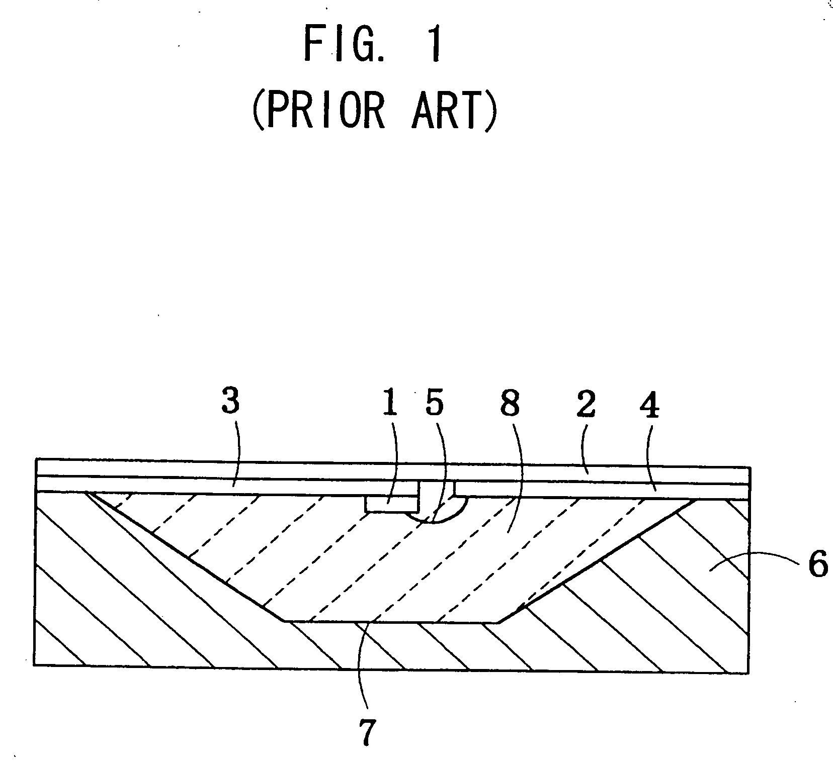
In a conventional light emission source in which a light emitting diode is sealed in a mold resin, light emitted from the light emitting diode to its front is emitted from the light emission source as it is, but light emitted in a diagonal direction from the light emitting diode is totally reflected on a boundary surface of the mold resin and scattered in an inside wall of a housing to be lost, resulting into deterioration of use efficiency of light.
This conventional light emission source, however, has the disadvantage that light reflected by the light reflecting member is obstructed by the light emitting diode and the lead frames when it is emitted forward, thereby producing shadows of these components and deteriorating the advantage of utilization of light near the optical axis center where quan

Method used


Image

  • Transparent optical component for light emitting/receiving elements
  • Transparent optical component for light emitting/receiving elements
  • Transparent optical component for light emitting/receiving elements

Examples


tenth embodiment

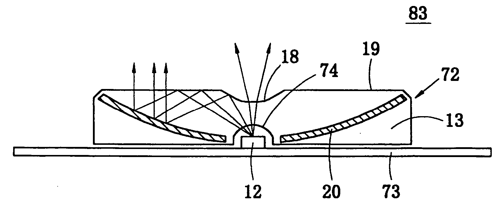
[0234]FIG. 16 is a sectional view of a light emission source 30 according to a tenth embodiment. In the light emission source 30 of this embodiment, a lens configuration of a lens-shaped direct emission region 18 is formed to be a Fresnel lens to decrease the thickness of the direct emission region 18 or the light emission source 30.

eleventh embodiment

[0235]FIG. 17 is a sectional view of a light emission source 31 according to an eleventh embodiment. In the light emission source 31 of this embodiment, a rear face of a mold resin 13 is formed to include a Fresnel lens on a surface of which a light reflecting portion 20 is formed. In this embodiment, the thickness of the light emission source 31 can be reduced.

twelfth embodiment

[0236]FIG. 18 is a sectional view of alight emission source 32 according to a twelfth embodiment. In this embodiment, a mirror 33 is disposed near a light emitter 12 within a mold resin 13 so as to reflect the light emitted sideway from the light emitter 12 toward a total reflection region 19. The light reflected by the mirror is totally reflected by the total reflection region 19, and further reflected by a light reflecting member 20 to be emitted forward from the total reflection region 19. If desired, the mirror 33 may be formed on an inner wall of a stem 15 (see FIG. 24).

[0237] According to this embodiment, the light emitted sideway in the light emitted from the light emitter 12 is directly reflected by the light reflecting portion 20 to be avoided from becoming lost light, whereby the light emitted in a side direction is effectively used and the use efficiency of light emitted from the light emitter 12 is further improved.


PUM


Abstract

This invention improves the use efficiency of light emitted by a solid light emitter such as a light emitting diode, and realizes a desired directional pattern. On a front boundary surface of a mold resin 13 sealing a light emitter 12, there are formed a direct emission region 18 for emitting the light from the light emitter 12 and a total reflection region 19 for totally reflecting the light from the light emitter 12. The direct emission region 18 is convex lens-shaped. A light reflecting portion 20 having a concave mirror shape is disposed on a rear wall of the mold resin 13. A part of light emitted from the light emitter 12 is emitted forward by receiving an optical lens action when it passes through the direct emission region 18. Another part of the light emitted by from the light emitter 12 is totally reflected by the total reflection region 19, and is reflected by the light reflecting portion 20, and emitted forward from the total reflection region 19.

Description

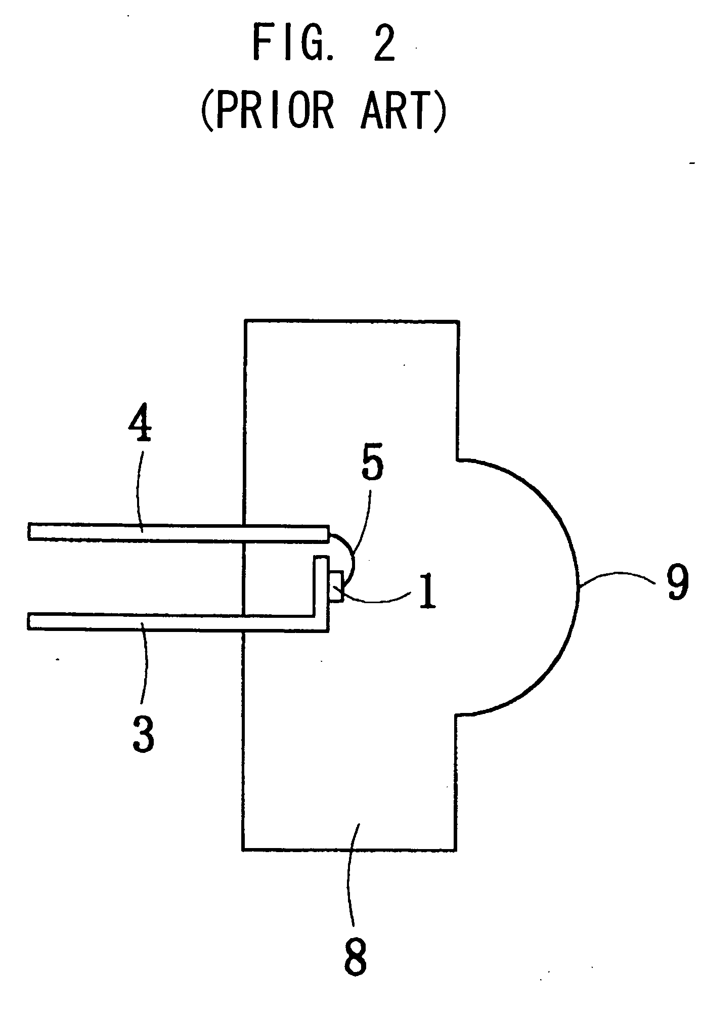
BACKGROUND OF THE INVENTION [0001] This invention relates to an optical device and an apparatus employing the optical device. (Light Emission Source) [0002] In a conventional light emission source in which a light emitting diode is sealed in a mold resin, light emitted from the light emitting diode to its front is emitted from the light emission source as it is, but light emitted in a diagonal direction from the light emitting diode is totally reflected on a boundary surface of the mold resin and scattered in an inside wall of a housing to be lost, resulting into deterioration of use efficiency of light. [0003] Heretofore, there has been proposed a light emission source capable of efficiently emitting the light emitted in a diagonal direction which is disclosed in the Japanese Laid-Open Patent Publication No. Hei 1-143368. FIG. 1 shows a sectional side view of a light emission source including a light emitting diode 1, a transparent glass substrate 2, lead frames 3 and 4, a bonding...

Claims


Application Information

Patent Timeline
IPC IPC(8): H01J3/14B60Q1/30E01F9/06F21S8/00G02B17/08H01L33/54H01L33/58H01L33/60
CPCB60Q1/302E01F9/065F21V5/04F21V7/0091F21W2111/00F21Y2101/02H01L33/54H01L33/58H01L33/60G02B19/0028G02B19/0061E01F9/559H01L2224/48091H01L2224/48247F21Y2115/10H01L2924/181H01L2924/1815H01L2924/00014H01L2924/00012
Inventor KIYOMOTO, HIRONOBUHOSOKAWA, HAYAMIYASUDA, NARUHOMMA, KENJITERAKAWA, YUKARI
Owner ORMON CORP
Why Eureka
Try Eureka