Pressure blast pre-filming spray nozzle

a spray nozzle and pre-filming technology, applied in the direction of check valves, machines/engines, combustible gas purification/modification, etc., can solve the problems of uneven and poorly controlled temperature reduction throughout, water buildup, structural failure,

Active Publication Date: 2006-06-15
IMI VISION LTD
View PDF15 Cites 26 Cited by
  • Summary
  • Abstract
  • Description
  • Claims
  • Application Information

AI Technical Summary

Benefits of technology

[0019] The combination of the conical valve seat and conical outer surface is effective to induce a conical spray pattern for the cooling water that is exiting the annular gap when the valve element is in the open position. Advantageously, the passage of cooling water through the valve apertures provides for a substantially uniformly distributed conically-shaped spray pattern wherein the spatial distribution of droplets is more uniform across a transverse cross sectional area of the spray pattern as compared to the spray pattern resulting from a valve body having no valve apertures.

Problems solved by technology

Because superheated steam can damage turbines or other downstream components, it is necessary to control the temperature of the steam.
In addition, a streaming spray of cooling water will pass through the superheated steam flow and impact the opposite side of the steam pipe, resulting in water buildup.
This water buildup can cause erosion and thermal stresses in the steam pipe that may lead to structural failure.
Likewise, a non-uniform spray pattern of cooling water will result in an uneven and poorly controlled temperature reduction throughout the flow of the superheated steam.
Furthermore, the inability of the cooling water spray to efficiently evaporate in the superheated steam flow may also result in an accumulation of cooling water within the steam pipe.
The accumulation of this cooling water will eventually evaporate in a non-uniform heat exchange between the water and the superheated steam, resulting in a poorly controlled temperature reduction.
However, the construction of this device is complex with many parts such that the device has a high construction cost.
Although this desuperheater device may eliminate the impaction of the cooling water spray on the steam pipe walls, such a device is necessarily complex, costly to manufacture and install and requires a high degree of maintenance after installation.

Method used


Image

  • Pressure blast pre-filming spray nozzle
  • Pressure blast pre-filming spray nozzle
  • Pressure blast pre-filming spray nozzle

Examples


first embodiment

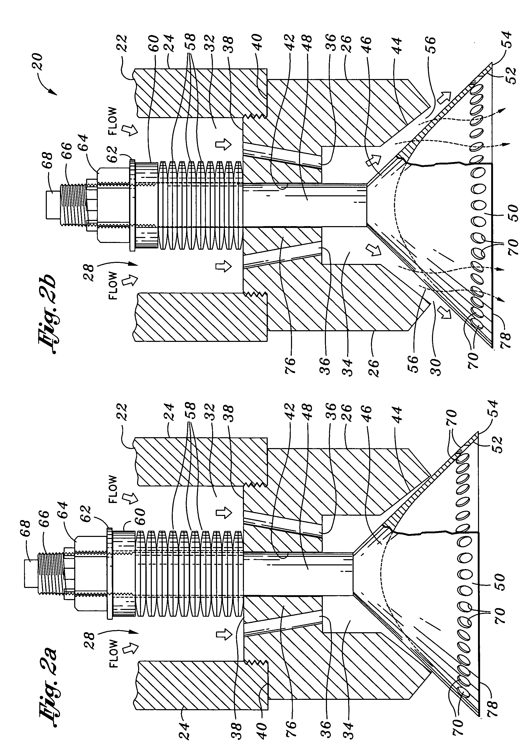
[0054] Although the valve apertures 70 of the first embodiment are shown as being generally axially aligned with the valve stem 48, the valve apertures 70 may be outwardly or inwardly angled or oriented relative to the valve stem 48. It has been shown that such outward or inward angling of the aperture axis of each one of the valve apertures 70 relative to the valve stem 48 provides a means to control the angle over which the cooling water spray exits the nozzle assembly 20. In addition, it is contemplated that the cross sectional shape of the valve apertures 70 may be provided in a variety of alternate configurations. For example, the valve apertures 70 may be configured with a generally elliptical cross sectional shape along the axial direction of the valve aperture 70.

[0055] Referring now to FIGS. 4 and 4a, shown is the valve element 78 in a second embodiment wherein the valve apertures 70 are arranged in two circumferential rows 72 with each valve aperture 70 in a circumferentia...

third embodiment

[0058] Referring now to FIGS. 5 and 5a, shown is the valve element 78 in a third embodiment wherein the valve apertures 70 are configured as a plurality of generally arcuate slots 74 arranged in a single circumferential row 72. As shown in FIG. 4a, the valve apertures 70 are configured as three arcuate slots 74 disposed in equidistantly spaced relation to each other about the outer surface 50. Such an arrangement promotes the formation of a uniform spray pattern for more even mixing of the cooling water spray within the flow of superheated steam. The slots 74 may be outwardly or inwardly angled or oriented relative to the valve stem 48 in a manner similar to that described above for the valve apertures 70. For example, the slots 74 may be axially aligned with the valve stem 48. However, the slots 74 may be oriented normal to the outer surface 50.

[0059] It has been shown that such outward or inward angling of the slots 74 relative to the valve stem 48 provides a means to control the ...

fourth embodiment

[0060] Referring now to FIGS. 6, 6a, and 6b, shown is the valve element 78 in a fourth embodiment wherein the valve element 78 has a valve body 46 with the valve stem 48 extending axially upwardly therefrom. The valve body 46 includes an upper body portion 88 and a ring portion 82 which is disposed in axially spaced relation to the upper body portion 88. As can be see in FIG. 6a, the ring portion 82 is interconnected to the upper body portion 88 by a plurality of spokes 80 which may extend radially outwardly from the upper body portion 88. The spacing between the upper body portion 88 and the ring portion 82 defines a plurality of valve apertures 70 which can be seen in FIGS. 6 and 6a. The upper body portion 88 has a conical outer surface 50 which is shaped similar to the embodiments shown in FIGS. 3-5 and which were described above.

[0061] Notably, the upper body portion 88 is specifically configured such that a conical spray pattern develops as a result of flow out of the annular g...


PUM

PropertyMeasurementUnit
half angleaaaaaaaaaa
seat half angleaaaaaaaaaa

Abstract

Disclosed is a nozzle assembly comprising a nozzle housing and a valve element axially slidable therewithin between a closed and an open position. The nozzle housing has a housing inlet and a housing outlet fluidly interconnected by a plurality of housing passages. The valve element has a truncated conical valve body including a conical outer surface and a concave inner surface with a plurality of valve apertures extending through the valve body. The outer surface is sealingly engagable to a valve seat formed in the housing outlet such that the flow of cooling water through the valve apertures is prevented when the valve element is in the closed position. The outer surface and valve seat collectively define an annular gap when the valve element is axially displaced to the open position such that a portion of the cooling water flowing through the annular gap may pass through the valve apertures.

Description

CROSS-REFERENCE TO RELATED APPLICATIONS [0001] The present application is a continuation-in-part application of pending U.S. patent application Ser. No. 10 / 795,013 entitled PRESSURE BLAST PRE-FILMING SPRAY NOZZLE and filed on Mar. 5, 2004, the entire contents of which is expressly incorporated by reference herein.STATEMENT RE: FEDERALLY SPONSORED RESEARCH / DEVELOPMENT [0002] (Not Applicable) BACKGROUND OF THE INVENTION [0003] The present invention pertains generally to steam desuperheaters and, more particularly, to a uniquely configured valve element for use in a nozzle assembly for a steam desuperheating device. The nozzle assembly is specifically adapted for creating a substantially uniformly distributed spray of cooling water for spraying into a flow of superheated steam in order to reduce the temperature thereof. [0004] Many industrial facilities operate with superheated steam that has a higher temperature than its saturation temperature at a given pressure. Because superheated ...

Claims


Application Information

Patent Timeline
Patent Type & Authority Applications(United States)
IPC IPC(8): B01F3/04
CPCB05B1/06B05B1/3006B05B1/3073Y10S261/13B05B7/0075F22G5/123B05B1/308Y10T137/7932
Inventor SHERIKAR, SANJAY V.KARLSSON, INGMAR
Owner IMI VISION LTD
Why Eureka
Try Eureka