Energy absorbing vehicle fender

Inactive Publication Date: 2006-06-15
SABIC INNOVATIVE PLASTICS IP BV
View PDF6 Cites 1 Cited by
  • Summary
  • Abstract
  • Description
  • Claims
  • Application Information

AI Technical Summary

Benefits of technology

[0010] Variations are set forth herein and it is contemplated that multiple design features of different shapes can be integr

Problems solved by technology

In order to comply with upcoming pedestrian safety requirements, in particular,

Method used


Image

  • Energy absorbing vehicle fender
  • Energy absorbing vehicle fender
  • Energy absorbing vehicle fender

Examples


Embodiment Construction

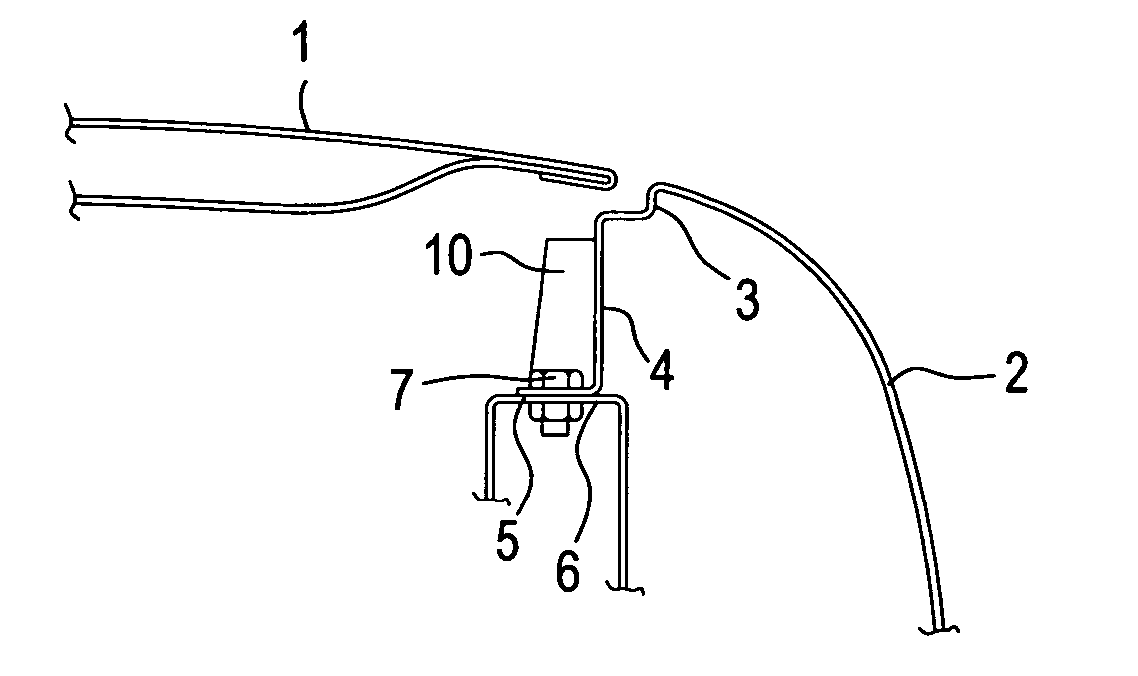
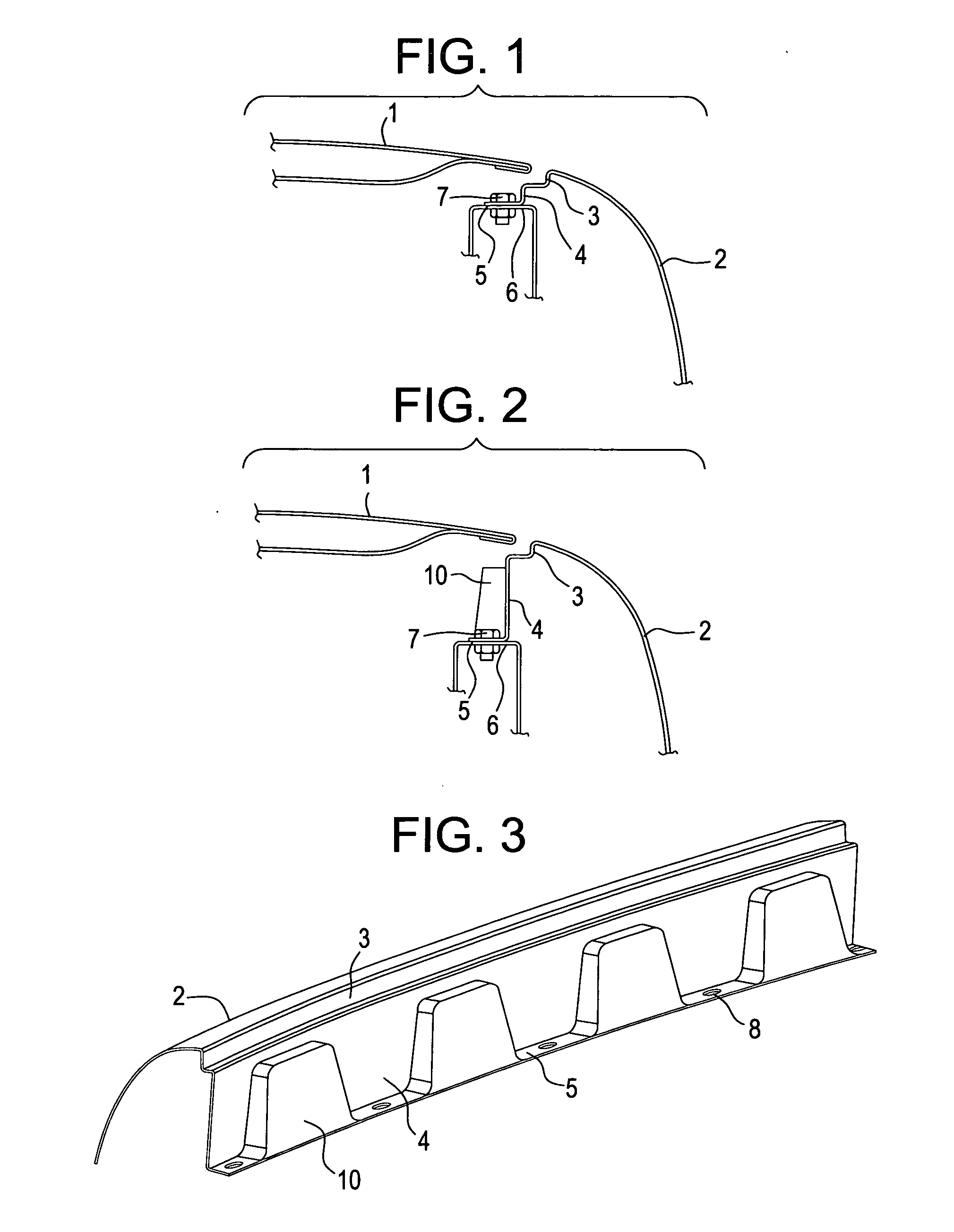
[0026]FIG. 1 shows partial cross sectional view of a typical prior art mounting of a metal fender 2, which is fixedly secured to support member 6 with a nut and bolt shown at 7. A hood is shown at reference number 1. The fender 2 includes a flanged portion having a vertically depending section 4 joined to a horizontally aligned section 5. As illustrated in FIG. 1, the height of vertically depending section 4 is relatively short so that the distance between the top of fender 2 and the rigid support member 6 is a relatively short distance so that very little space is provided for intrusion of an object during impact before the rigid support member 6 is contacted.

[0027]FIG. 2 illustrates an embodiment where the height of the vertically aligned section 4 of the attachment flange is sufficient to permit the fender 2 to crush upon impact while providing for clearance of support member 6 from the intruding object. The fender 2 includes an exteriorly facing portion having an aesthetic exte...


PUM


Abstract

A fender for absorbing forces generated from an impact includes a depending attachment flange which comprises a vertically aligned section depending from an exterior portion of the fender and a horizontally aligned section depending from the vertically aligned section adapted for mounting to a vehicle wherein the vertically aligned section includes a plurality of contoured portions for enhancing the stiffness of the vertically aligned section.

Description

CROSS REFERENCE TO RELATED APPLICATIONS [0001] This application is a continuation in part of U.S. patent application PCT / US04 / 29279 and claims rights of priority under 35 U.S.C. 19 from U.S. patent application Ser. No. PCT / US04 / 29279 filed on Sep. 3, 2004 and U.S. Provisional Application Ser. No. 60 / 500633 filed on Sep. 5, 2003, which are incorporated herein by reference in its entirety.FIELD OF INVENTION [0002] The invention relates to a vehicle fender of the type that is adaptable for pedestrian protection. BACKGROUND OF THE INVENTION [0003] Future legislation in Japan and European countries may require an energy absorbent design for vehicle fender systems to help protect a pedestrian's head and body from impact with an automotive fender. [0004] Typically, a metal fender is attached to the body of vehicle through a rigid support member sometimes referred to as a shotgun or apron panel. This rigid member, which extends lengthwise of the vehicle, is typically connected to the frame ...

Claims


Application Information

Patent Timeline
IPC IPC(8): B62D25/16B60R21/34
CPCB60R21/34B60R2021/343B62D25/105B62D25/16B62D25/163
Inventor MARIJNISSEN, KEESGILSING, ROY
Owner SABIC INNOVATIVE PLASTICS IP BV
Why Eureka
Try Eureka