Timer switch

a timer switch and switch technology, applied in the direction of contact mechanisms, electrical apparatus casings/cabinets/drawers, instruments, etc., can solve the problem of more troublesome installation

Inactive Publication Date: 2006-06-15
LAI LUI DAVID PING
View PDF2 Cites 28 Cited by
  • Summary
  • Abstract
  • Description
  • Claims
  • Application Information

AI Technical Summary

Benefits of technology

[0004] Therefore, the primary objective of the present invention is t

Problems solved by technology

Due to the structural factor, a traditional timer is controlled by two lines: a power

Method used


Image

  • Timer switch
  • Timer switch
  • Timer switch

Examples


Embodiment Construction

[0013] To make it easier for our examiner to understand the objective of the invention, its structure, innovative features, and performance, we use a preferred embodiment together with the attached drawings for the detailed description of the invention.

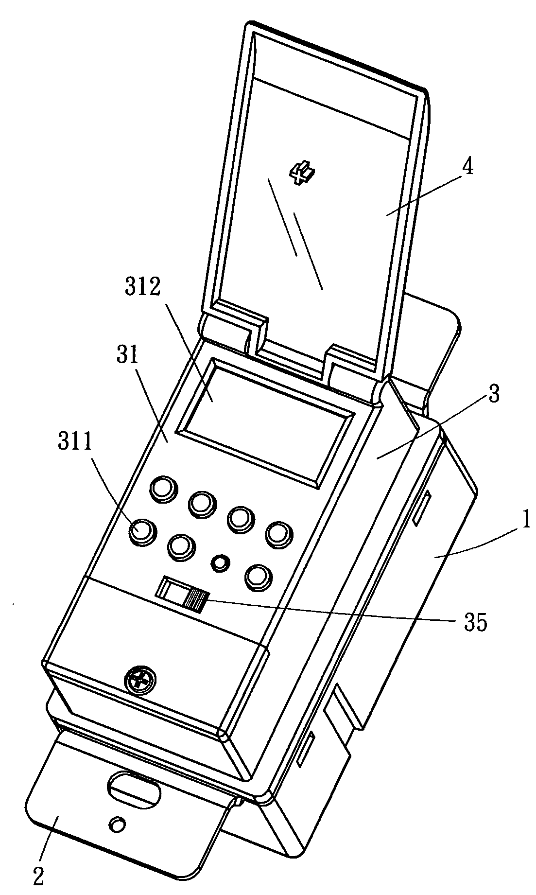
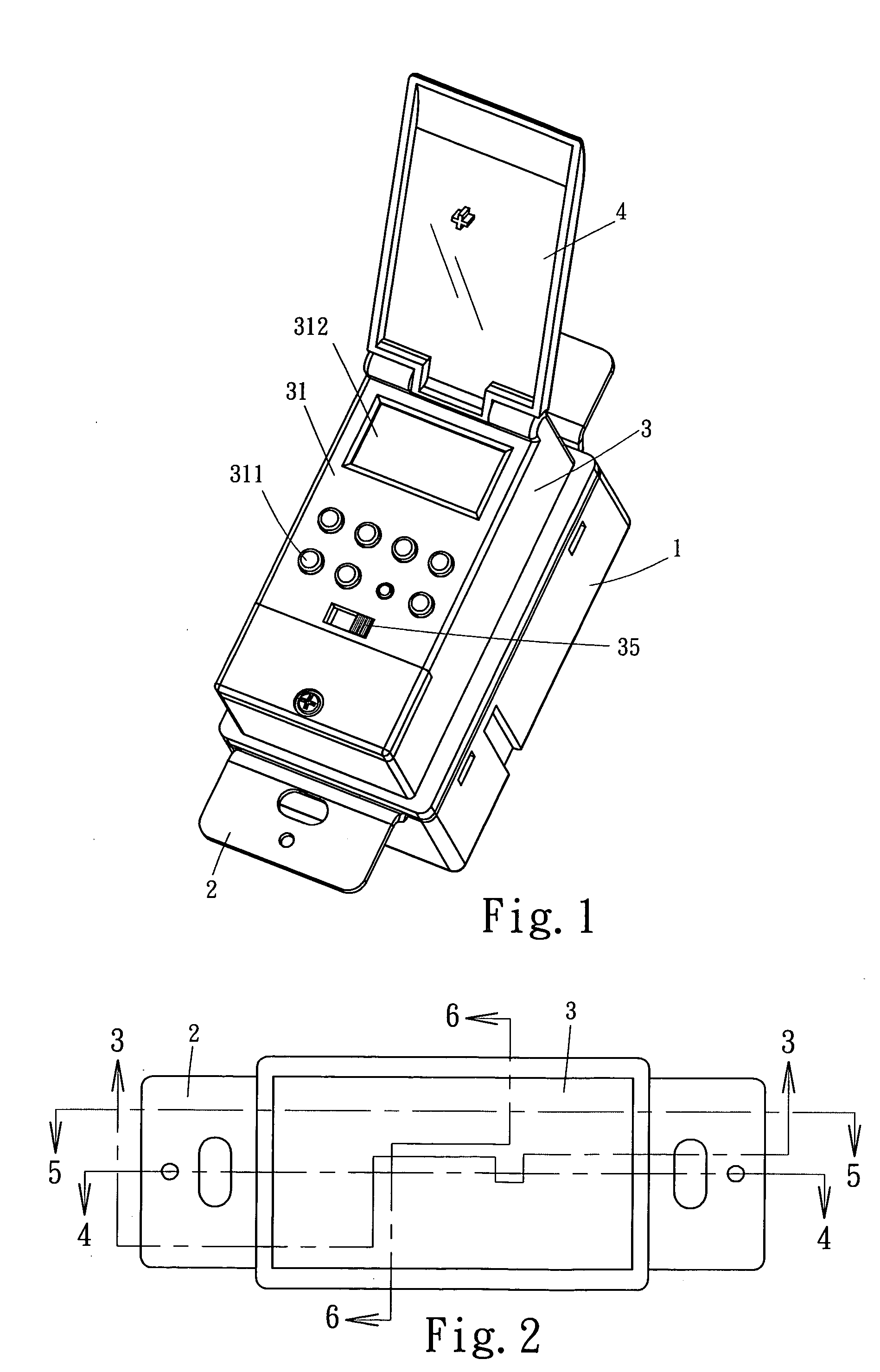
[0014] In FIG. 1, the timer switch of the present invention comprises a lower casing bottom chassis 1, a fixing board 2, an upper casing 3 and a transparent external panel 4. The fixing board 2 is built into the top of the lower casing 1 to be fixed onto a wall, and the top of the fixing board 2 fixes the upper casing 3 into its position. The upper casing 3 has an operating panel 31 on its surface, and an external transparent panel 4 that can be rotated and opened.

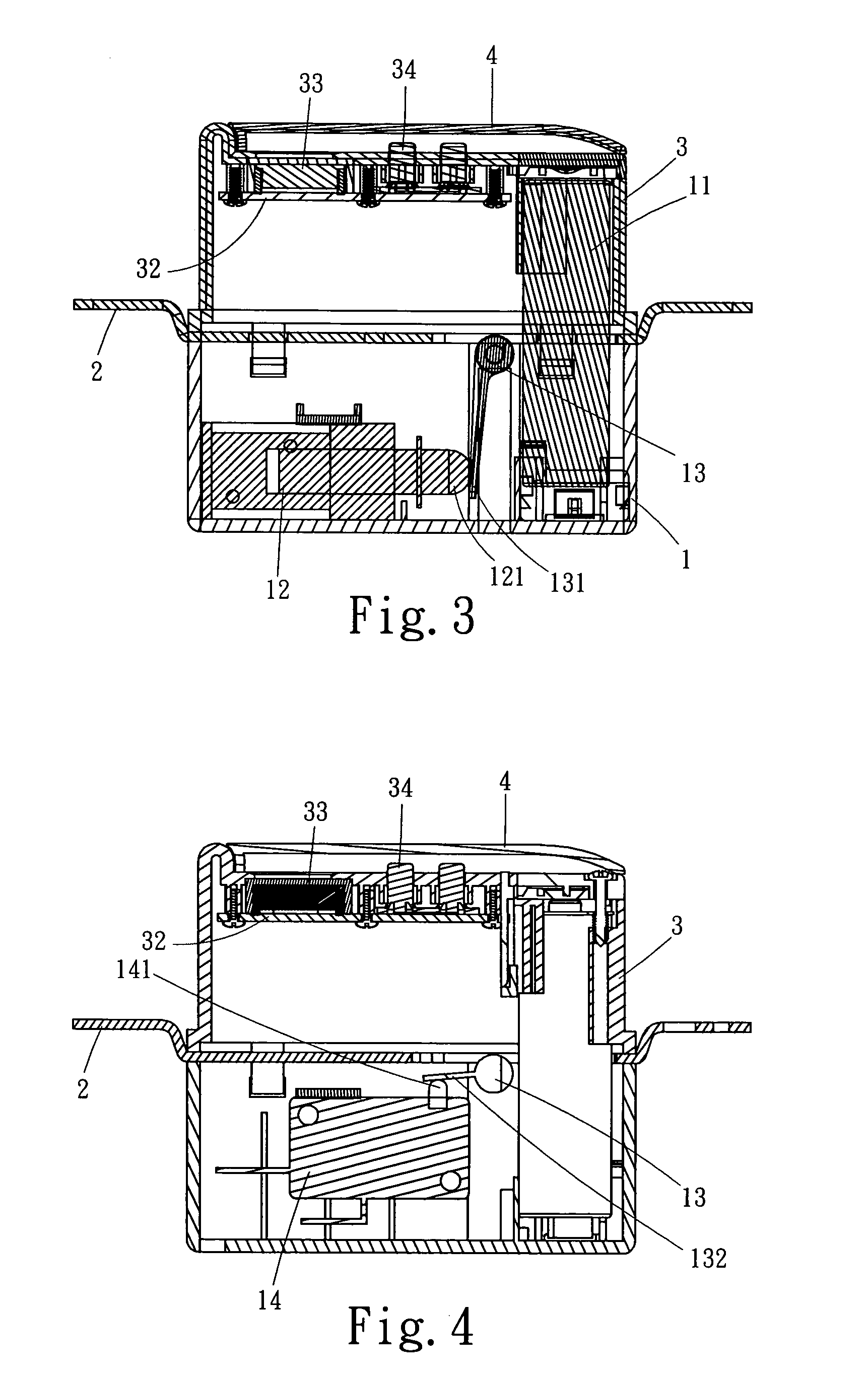
[0015] In FIGS. 2 to 5, a size AA battery module 11 is installed on one side in the space between the upper casing 1 and the lower casing 3, and a circuit board 32 is installed in the upper casing 3. The circuit board 32 comprises an LCD display panel 33 and a rubber press...


PUM


Abstract

The present invention discloses a timer switch that uses an integrated circuit to control the time and a self-locking electromagnetic coil solenoid valve to drive the operation of a microswitch, which is particularly applicable to be installed on a wall as a timer switch. The switch device uses the electronic control of two 1.5V AA batteries to enter a set time through input keys, and a CPU will issue a pulse with very short timing of 30 ms to the solenoid to produce a magnetic field to drive a turning rod and open a primary switch in order to turn on or off a circuit.

Description

FIELD OF THE INVENTION [0001] The present invention relates to a timer switch, more particularly to a timer switch device being installed onto a wall and using an integrated circuit (IC) to control the time and a self-locking electromagnetic coil solenoid valve to drive a primary switch to move. The switch device installs two 1.5V AA batteries and sets the time directly from a plurality of external input keys, such that when the time is set, an integrated circuit (IC) issues a very short timing of 30 ms to the solenoid valve to drive the solenoid to produce a magnetic field and drive the primary switch to turn on or off a circuit. BACKGROUND OF THE INVENTION [0002] In many occasions, an external accessory or a specific device is used in a regular manner, such as a lamp that provides illumination, a cooling system, an inspecting instrument or a ventilator is run at a fixed time. Therefore, such device can be turned on or off by a timer switch instead of being operated manually. On on...

Claims


Application Information

Patent Timeline
IPC IPC(8): H01H33/59
CPCH01H43/00H01H50/545H01H2300/03Y02B90/224Y04S20/14Y02B90/20
Inventor LAI LUI, DAVID PING
Owner LAI LUI DAVID PING
Why Eureka
Try Eureka