
Illumination apparatus for display device using hologram-based light guide plate (LGP)

a technology of light guide plate and illumination apparatus, which is applied in the direction of lighting and heating apparatus, planar/plate-like light guide, instruments, etc., can solve the problem of low diffraction efficiency of conventional lcd backlight, and achieve the highest diffraction efficiency and improve light utilization efficiency

Active Publication Date: 2006-06-15
SAMSUNG DISPLAY CO LTD
View PDF6 Cites 75 Cited by
  • Summary
  • Abstract
  • Description
  • Claims
  • Application Information

AI Technical Summary

Benefits of technology

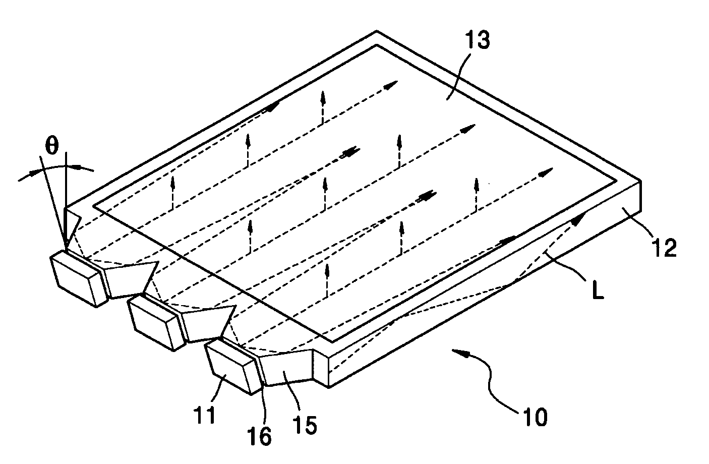
The present invention provides an illumination apparatus for a display device using a hologram-based LGP that improves light utilization efficiency by permitting a ray emitted from a point light source to be incident on the hologram pattern at an altitude angle for which diffraction efficiency is the highest. The LGP has a hologram pattern on its top surface, and the point light source is disposed on the side of the LGP facing the hologram pattern. The LGP may also have a hologram pattern on its bottom surface, and a reflector may reflect the light exiting from the bottom surface onto the top surface. The illumination apparatus may also include a collimator that collimates the light emitted from the point light source into a parallel beam so that it is incident on the hologram pattern at an azimuth angle for which diffraction efficiency is the highest. The refracting element may include a first and second inclined surface to refract the light emitted from the point light source towards the top or bottom surface of the LGP. The method involves emitting light onto the side of the LGP with a hologram pattern on the top surface, and exiting a portion of the incident light from the top surface through the hologram pattern. The method may also involve disposing another hologram pattern on the bottom surface, reflecting a remaining portion of the incident light from the top surface, and reflecting the remaining portion of the light from the bottom surface onto the top surface.

Problems solved by technology

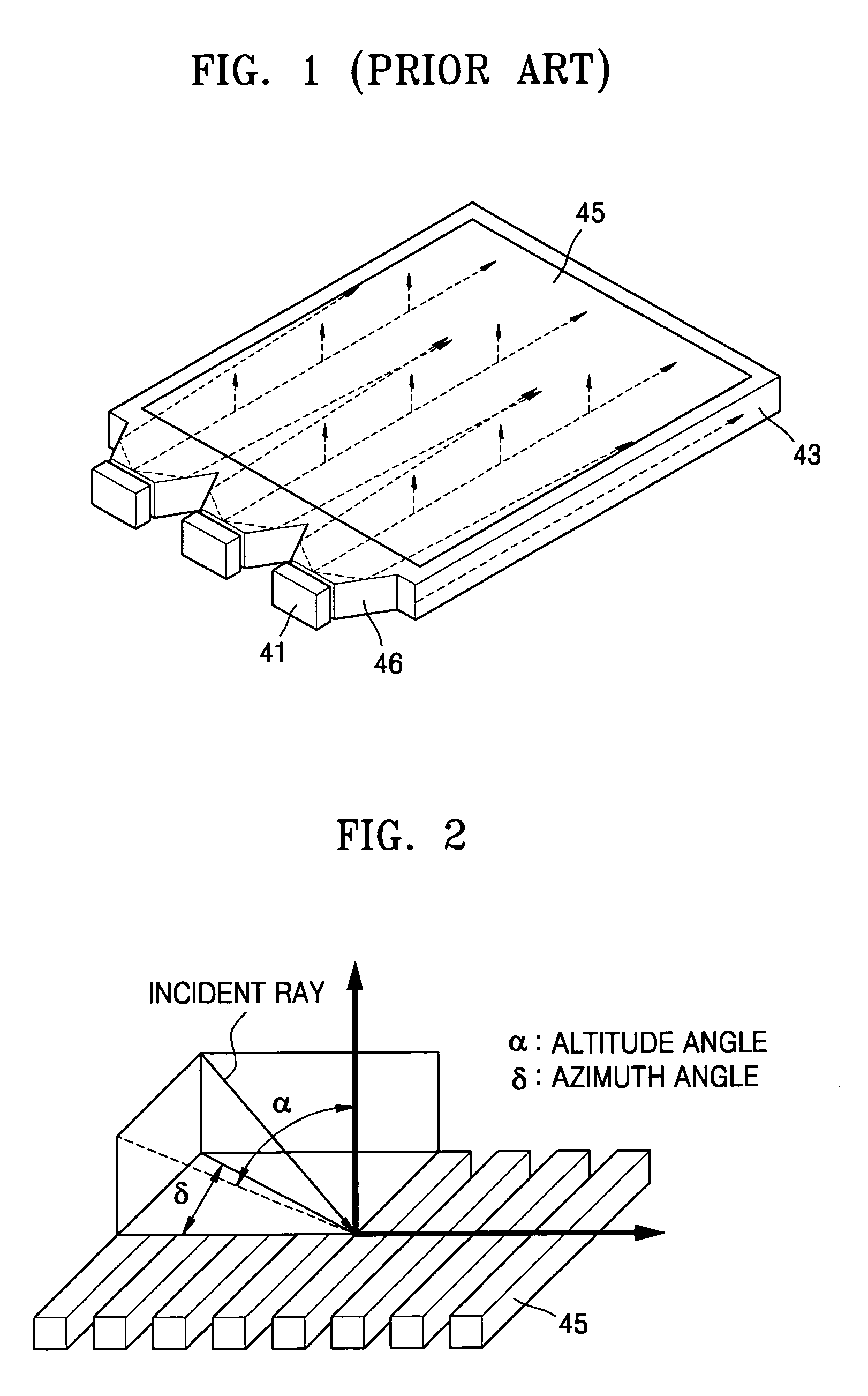
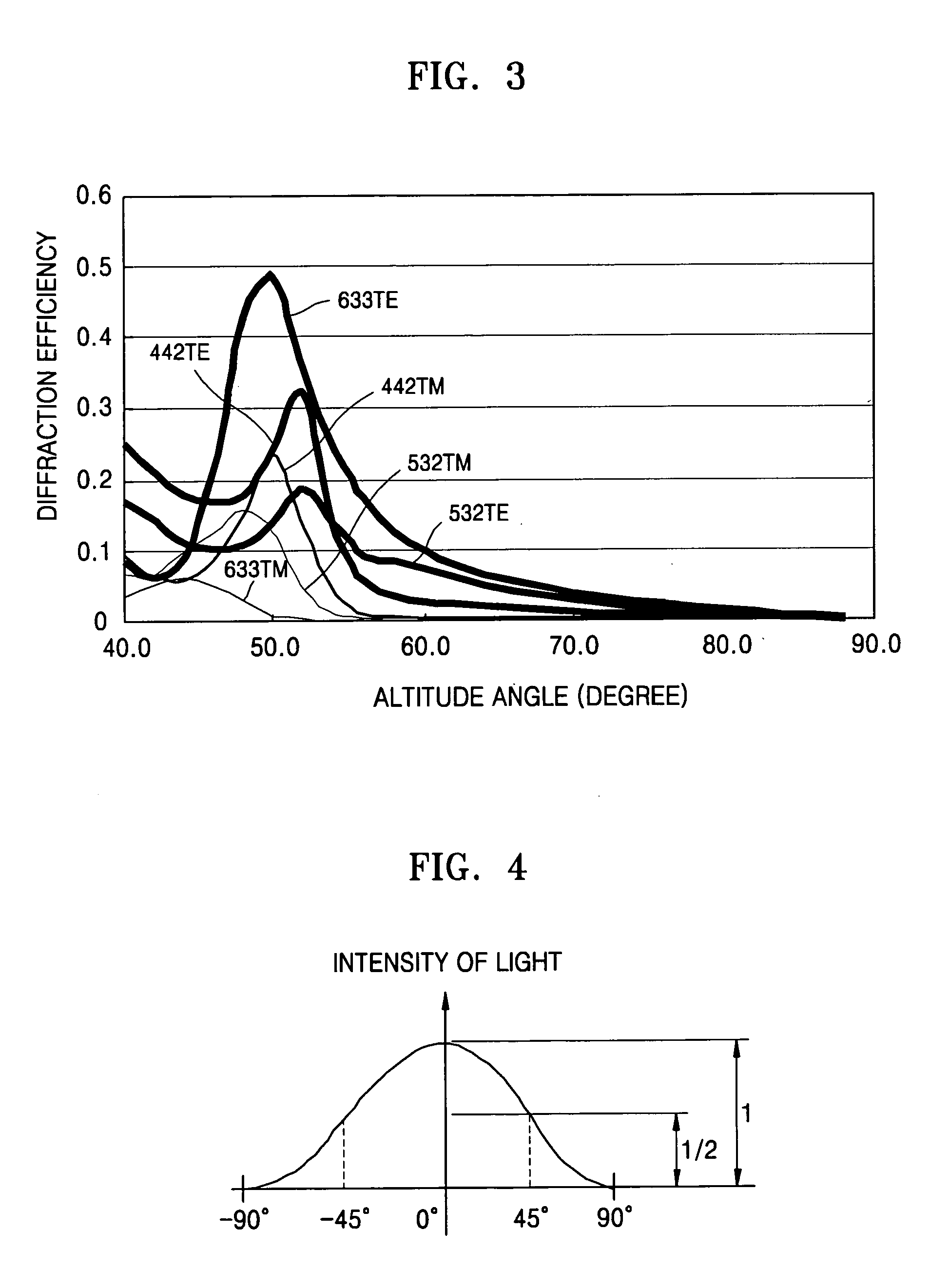
However, the conventional LCD backlight provides low diffraction efficiency because a highest-intensity incident ray is incident on the hologram pattern 45 at an altitude angle of 90°.

Method used


Image

  • Illumination apparatus for display device using hologram-based light guide plate (LGP)
  • Illumination apparatus for display device using hologram-based light guide plate (LGP)
  • Illumination apparatus for display device using hologram-based light guide plate (LGP)

Examples


Embodiment Construction

[0031] The configurations and operations of illumination apparatuses for a display device according to exemplary embodiments of the present invention will now be described in detail with reference to the accompanying drawings.

[0032] As described earlier with reference to FIG. 3, when light emitted from a point light source is incident upon a hologram pattern from a specific altitude angle, e.g., about 50°, the incident light can be diffracted with highest efficiency. Thus, the present invention proposes a hologram-based LGP constructed such that light emitted by the point light source can be incident obliquely on the hologram pattern at an altitude angle for which diffraction efficiency is high.

[0033] Referring to FIG. 5A, an illumination apparatus 10 for a display device according to a first exemplary embodiment of the present invention includes a plurality of point light sources 11 and a LGP 12 having a hologram pattern 13 at the top surface thereof. The plurality of point light...


PUM


Abstract

An illumination apparatus and method for a display device designed such that light is incident on a hologram or hologram pattern at an angle for which diffraction efficiency is the highest. The illumination apparatus includes at least one point light source which emits light and a light guide plate (LGP) which has the at least one point light source disposed on a side thereof and a hologram pattern on a top surface which permits the light incident from the point light source to exit from the top surface. The side of the LGP facing the point light source is inclined such that the light is incident obliquely on the hologram pattern at an altitude angle which provides high diffraction efficiency.

Description

CROSS-REFERENCE TO RELATED PATENT APPLICATION [0001] This application claims priority from Korean Patent Application No. 10-2004-0105649, filed on Dec. 14, 2004, in the Korean Intellectual Property Office, the disclosure of which is incorporated herein in its entirety by reference. BACKGROUND OF THE INVENTION [0002] 1. Field of the Invention [0003] Apparatuses and methods consistent with the present invention relate to an illumination apparatus and method for a display device, and more particularly, to an illumination apparatus and method for a display device constructed such that an incident ray impinges upon a hologram or hologram micro-pattern at an angle which provides high diffraction efficiency. [0004] 2. Description of the Related Art [0005] Non-emissive displays such as liquid crystal displays (LCDs) typically require a separate light source such as an LCD backlight. The LCD backlight needs to provide a uniform illumination. [0006]FIG. 1 schematically shows a conventional LC...

Claims


Application Information

Patent Timeline
Patent Type & Authority Applications(United States)
IPC IPC(8): G02B5/32
CPCG02B5/32G02B6/0018G02B6/0033G02B6/0043G02B27/0944G02F1/133615G02F2203/22G02F1/1335
Inventor CHOI, JIN-SEUNG
Owner SAMSUNG DISPLAY CO LTD
Learn More