Etendue efficient combination of multiple light sources

a multi-colored light source and efficient technology, applied in the field of multi-colored illumination, can solve the problems of compromising the projector's goal of producing a high intensity output, consuming a lot of light energy, and consuming a lot of energy, so as to achieve the effect of increasing etendue and not increasing etendu

Inactive Publication Date: 2006-06-15
MEADOWSTAR ENTERPRISES
View PDF23 Cites 34 Cited by
  • Summary
  • Abstract
  • Description
  • Claims
  • Application Information

AI Technical Summary

Benefits of technology

[0008] The polarization recovery waveguide system of the present invention combines the above-enumerated list of optical components into a single, compact unit. In one embodiment, the waveguide polarization recovery system further includes one or more “gaps” of optically clear material positioned between the optical components to encourage the occurrence of total internal reflection that minimizes the loss of the optical energy by the system.
[0010] In accordance with an embodiment of the present system, a multi-colored illumination system comprising a beam combiner. The beam combiner comprises two triangular prisms and a filter for transmitting a first light and reflecting a second light, each light having a different wavelength. The beam combiner combines the transmitted first light and the reflected light to provide a combined beam. Each surface of the triangular prisms is polished, thereby combining the lights without increasing etendue of the multi-colored illumination system.
[0011] In accordance with an embodiment of the present invention, a multi-colored illumination system comprises n beam combiners for combining n+1 lights, where N>2, each light having a different wavelength, and a low index glue or air gap provided between each beam combiner. Each beam combiner comprises two triangular prisms, each surface of the triangular prisms being polished and a filter for transmitting a combined beam received from a previous beam combiner and reflecting a new light from n+1 lights which has not been previously transmitted or reflected. The beam combiner combines the transmitted combined beam and the reflected new light to provide a new combined beam. The new combined beam is provided to the next beam combiner if the beam combiner is not the last beam combiner or outputs the new combined beam if the beam combiner is the last beam combiner. The low index glue or air gap between each beam combiner enables the multi-colored illumination system to combined all of the lights without increasing etendue of the multi-colored illumination system.
[0012] In accordance with an embodiment of the present invention, a multi-colored illumination system comprises at least two LEDs, a light pipe associated with each LED, an X-cube and a low index glue or air gap. The two LEDs provide two lights having two different wavelengths. The X-cube combines the lights received from each light pipe associated with a LED to provide an output beam. The low index glue or air gap is provided between each of the light pipe and the X-cube, thereby combining the lights without increasing etendue of the multi-colored illumination system.
[0015] In accordance with an embodiment of the present invention, a method for multi-colored illumination comprises the steps of combining by a first beam combiner a first light transmitted by a first filter and a second light reflected by the first filter to provide a combined beam; combining by a second beam combiner the combined beam transmitted by a second filter and a third light reflected by the second filter to provide an output beam, each light having different wavelength; and providing a low index glue or air gap between the beam combiners, thereby combining the lights without increasing etendue.
[0016] In accordance with an embodiment of the present invention, a method for multi-colored illumination comprises the steps of combining by an X-cube at least two lights having two different wavelengths received from corresponding two light pipes; and providing a low index glue or air gap between each light pipe and the X-cube, thereby combining the lights without increasing etendue.

Problems solved by technology

Unfortunately, the implementation of these known methodologies requires complex, bulky systems, which usually include 2-dimensional lens arrays and an array of polarization beam splitters.
Furthermore, the known methodologies lose much of the light energy and, therefore, compromise the projector's goal of producing a high intensity output.

Method used


Image

  • Etendue efficient combination of multiple light sources
  • Etendue efficient combination of multiple light sources
  • Etendue efficient combination of multiple light sources

Examples


Embodiment Construction

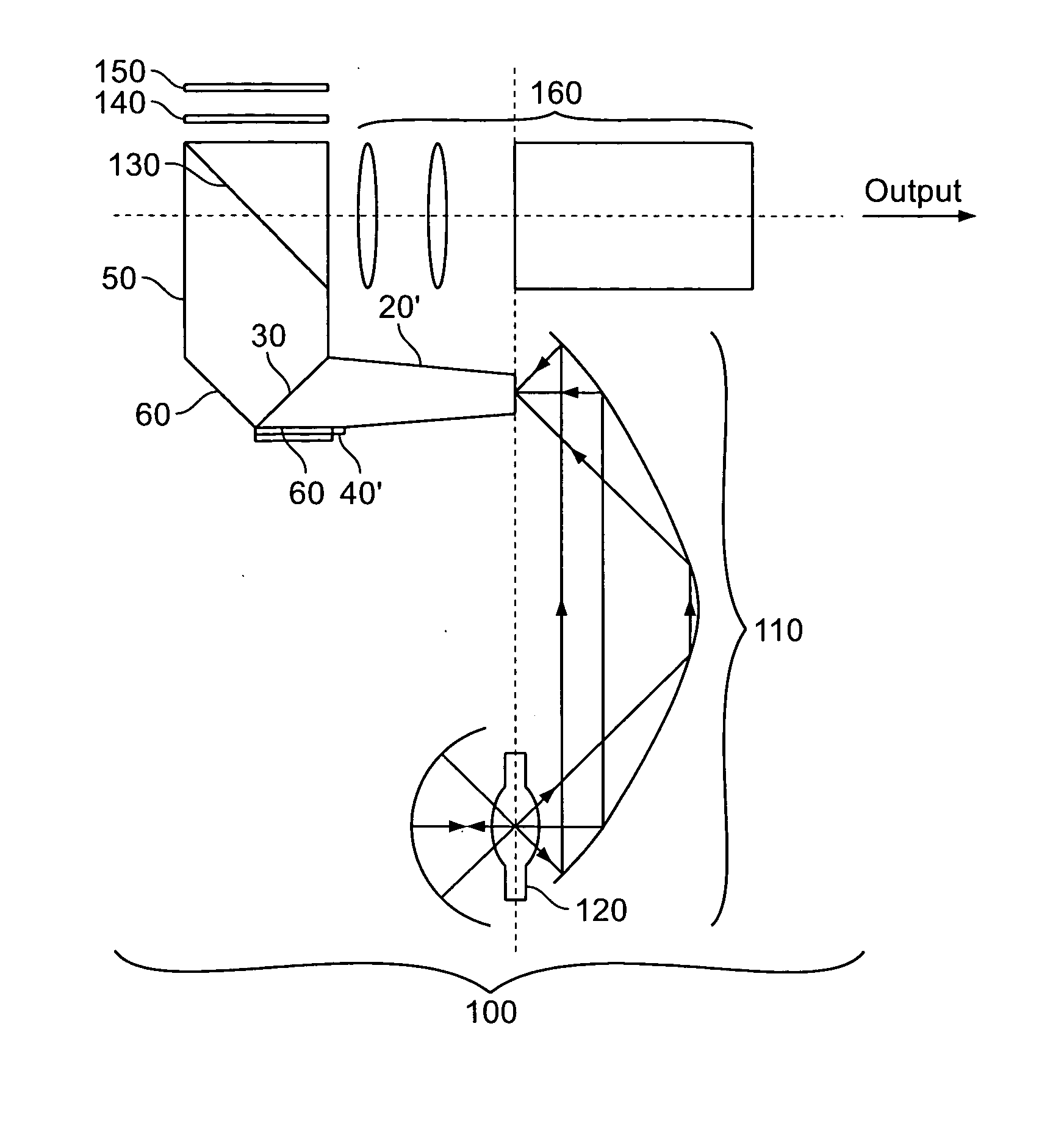
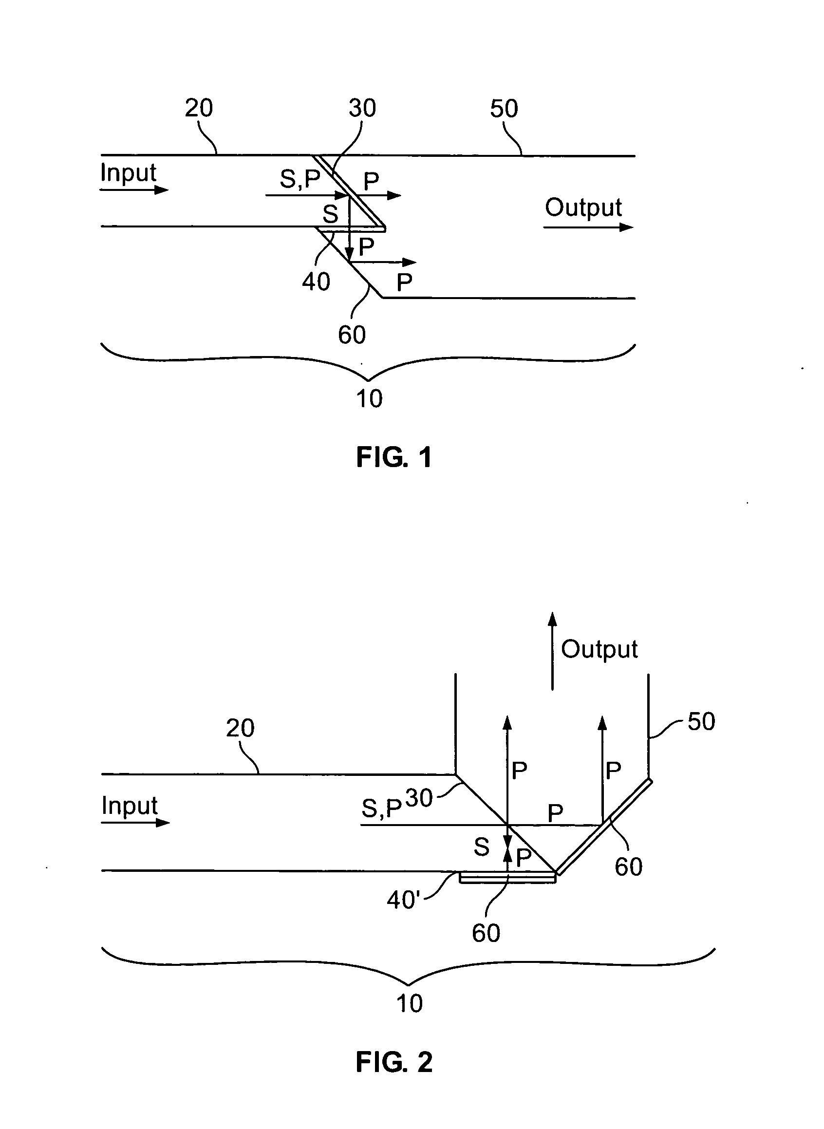
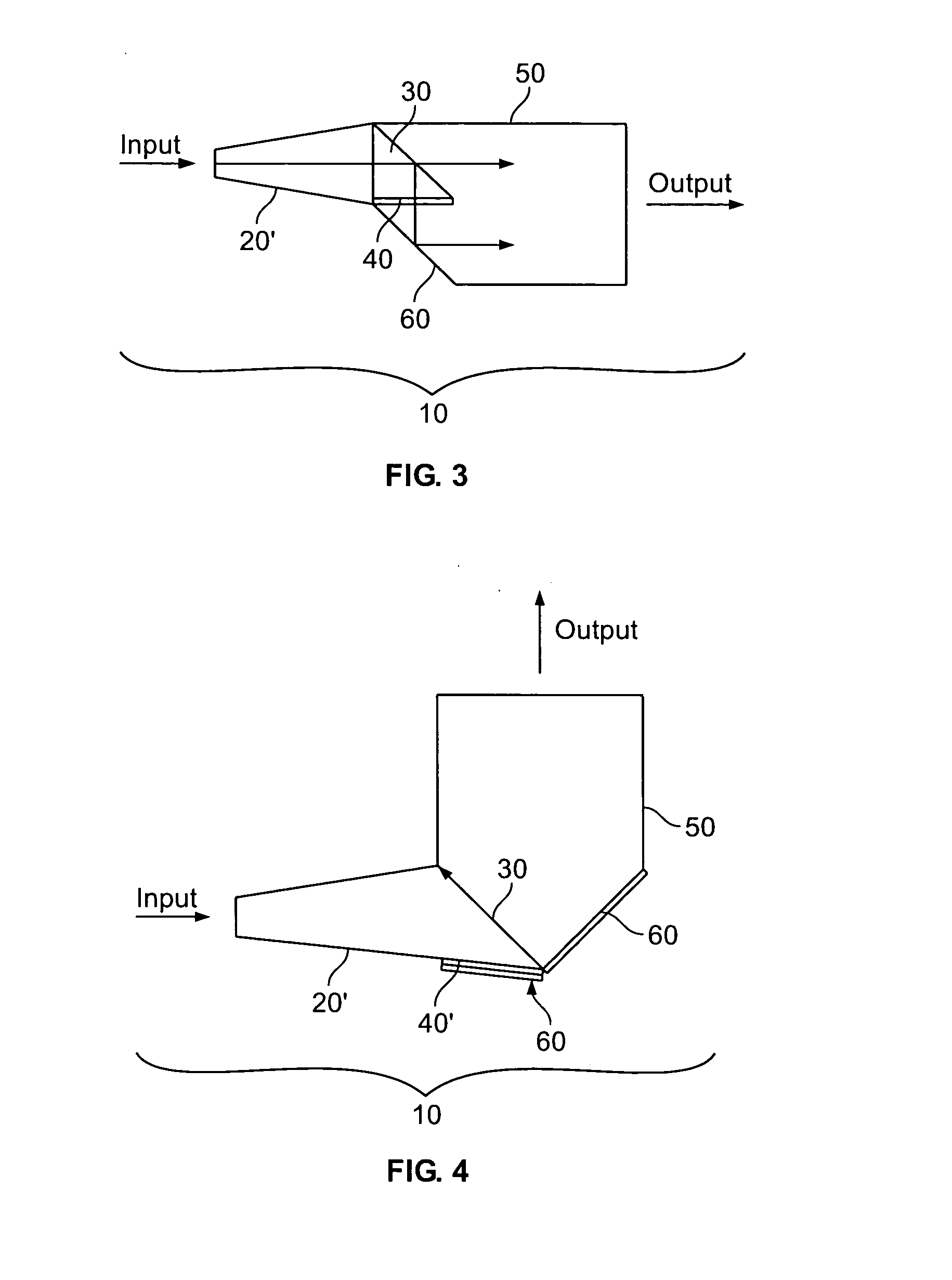
[0030] As illustrated in FIGS. 1-4 and 6-10, in accordance with embodiments of the present invention, a compact waveguide polarization recovery system 10 comprises an input waveguide 20, a polarizing beam splitter (“PBS”) 30, a wave plate 40, which can be a half-wave plate, or a quarter-wave plate depending on the configuration, and an output waveguide 50. The waveguide polarization recovery system 10 generally further includes mirrors 60 as needed to direct the light stream between the input and output waveguides, 20 and 50. The following discussion first summarizes several possible configurations for the waveguide polarization recovery system 10 and then describes the individual elements in greater detail.

[0031]FIGS. 1, 3, and 6 illustrate one configuration of the waveguide polarization recovery system 10 in which the output light energy is substantially parallel with the input light energy. In this embodiment, the input waveguide 20 introduces unpolarized input light from a ligh...


PUM


Abstract

A multi-colored illumination system comprising a beam combiner. The beam combiner comprises two triangular prisms and a filter for transmitting a first light and reflecting a second light, each light having a different wavelength. The beam combiner combines the transmitted first light and the reflected light to provide a combined beam. The six surfaces of each of the triangular prism of the beam combiner is polished, thereby combining the lights without increasing etendue of the multi-colored illumination system.

Description

CROSS REFERENCE TO RELATED APPLICATIONS [0001] The present application claims benefit of U.S. Provisional Application No. 60 / 651,079 filed Feb. 9, 2005, and the present application is a continuation-in-part of application Ser. No. 11 / 240,169 filed Sep. 30, 2005, which is a continuation of application Ser. No. 10 / 347,522 filed Jan. 21, 2003, now U.S. Pat. No. 6,982,830, which is a continuation of application Ser. No. 09 / 814,970, filed Mar. 23, 2001, now U.S. Pat. No. 6,587,269 which claims benefit of U.S. Provisional Application No. 60 / 227,312 filed Aug. 24, 2000 and 60 / 246,683 filed Nov. 8, 2000, all of which are incorporated by reference in their entireties.FIELD OF THE INVENTION [0002] The present invention relates an improved system and methodology for providing multi-colored illumination without increasing the etendue of the system. BACKGROUND OF INVENTION [0003] A liquid crystal display (hereafter “LCD”) is a known device used to control the transmission of polarized light ener...

Claims


Application Information

Patent Timeline
Patent Type & Authority Applications(United States)
IPC IPC(8): G02B27/28
CPCG02B27/1033G02B27/145G02B27/149
Inventor LI, KENNETH K.
Owner MEADOWSTAR ENTERPRISES
Why Eureka
Try Eureka