Internet broadcasting system and method thereof

a technology of internet broadcasting and broadcasting service provider, applied in the field of internet broadcasting system, can solve the problems of difficult multicasting address allocation, difficult to allocate multicasting number, and difficulty in identifying internet broadcasting service providers, and achieve the effect of reducing network load and increasing bandwidth

Inactive Publication Date: 2006-06-15
ELECTRONICS & TELECOMM RES INST
View PDF6 Cites 144 Cited by
  • Summary
  • Abstract
  • Description
  • Claims
  • Application Information

AI Technical Summary

Benefits of technology

[0020] It is, therefore, an object of the present invention to provide an Internet broadcasting system with decreased network loads and increased bandwidth by selectively transmitting a specifically requested broadcasting channel through using a router or switch for relaying or switching a broadcasting signal to a user terminal and a method thereof.

Problems solved by technology

It is generally difficult for an Internet broadcasting service provider to be allocated with a number of multicasting addresses for use in IP broadcasting.
Hence, it may also be difficult to allocate the multicasting address for use in IP broadcasting for each channel provided by the Internet broadcasting service provider.
Also, even though such multicasting address is allocated for each channel, thereby providing an effect of distinguishing the channels from each other, there may be still a problem of using many IP addresses.
Accordingly, the conventional Internet broadcasting method results in heavy loads to a network, thereby causing several problems such as incapability in accessing to and communicating with the terminal, a data loss, a reduction in communication speed, a terminal disconnection.
For instance, assuming that network processing capability of the terminal is 100 Mbps and the Internet broadcasting server 12 sends more than 5 high-quality broadcasting channels with 20 Mbps, the terminal may still have an operation difficulty due to an unnecessary traffic even though the terminal can process the corresponding broadcasting channel.

Method used


Image

  • Internet broadcasting system and method thereof
  • Internet broadcasting system and method thereof
  • Internet broadcasting system and method thereof

Examples


Embodiment Construction

[0033] Reference will now be made in detail to the preferred embodiments of the present invention, examples of which are illustrated in the accompanying drawings.

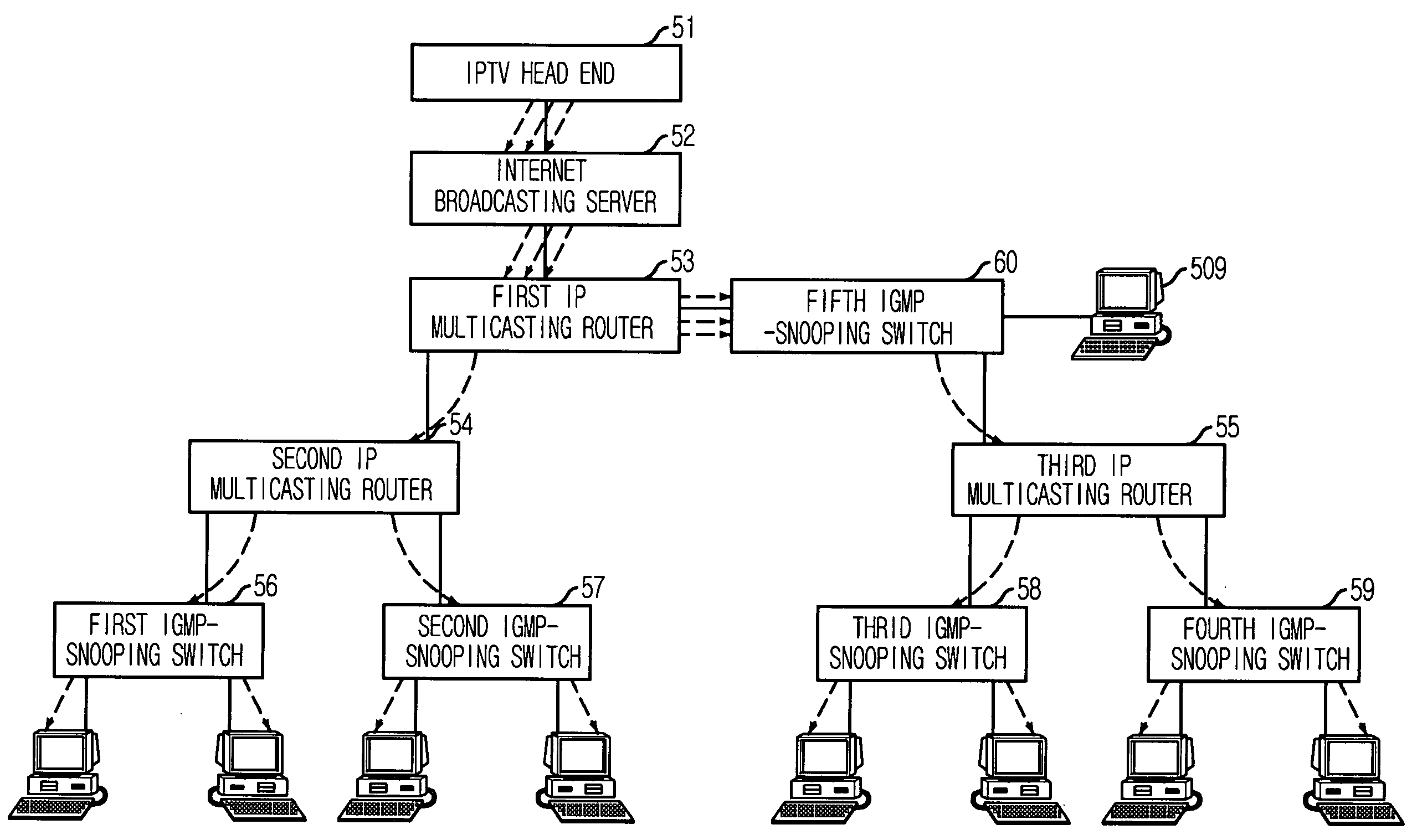
[0034]FIG. 5 is a configuration diagram showing one embodied Internet broadcasting system in accordance with the present invention.

[0035] As shown, the Internet broadcasting system includes: an IPTV head end 51; an Internet broadcasting server 52; a first to a third IP multicasting routers 53 to 55; and a first to a fifth IGMP-snooping switches 56 to 60. The IPTV head end 51 receives a cable broadcasting or terrestrial broadcasting signal and converts the received cable broadcasting or terrestrial broadcasting signal into a digital broadcasting signal. The Internet broadcasting server 52 stores the digital broadcasting signal into a recording medium and sending the stored digital broadcasting signal. The first to the third IP multicasting routers 53 to 55 relay the received broadcasting data, i.e., the digital broadcastin...


PUM


Abstract

An Internet broadcasting system and a method thereof are provided. The Internet broadcasting system includes: a signal converter for converting a received analog broadcasting signal into a digital broadcasting data; an Internet broadcasting unit for storing and sending the digital broadcasting data; a repeater for relaying the digital broadcasting data to a switching unit connected with a terminal according to a broadcasting request message inputted from the terminal but selectively relaying a channel selected by the terminal by referring to a first multicasting forwarding table created by using a UDP port number extracted from the broadcasting request message; and the switching unit for snooping on the broadcasting request message, extracting the UDP port number, storing the extracted UDP port number into a second multicasting forwarding table, and transmitting the digital broadcasting data of the selected channel to the corresponding terminal referring to an entry of the second multicasting forwarding table.

Description

FIELD OF THE INVENTION [0001] The present invention relates to an Internet broadcasting system and a method thereof; and, more particularly, to an Internet broadcasting system with reduced network loads and increased bandwidth by selectively transmitting a channel requested by a user terminal through using a router and a switch for routing and switching a broadcasting signal to the user terminal and a method thereof. DESCRIPTION OF THE RELATED ART [0002] A conventional Internet broadcasting system provides high-capacity broadcasting contents to a plurality of user terminals by employing an Internet protocol (IP) multicasting method. Especially, the IP multicasting method sets a specific Internet address in a region of “Class D” as a multicasting address for use in IP broadcasting specified by an international standardization association and enables simultaneous transmission of data, sent from a specific terminal sharing the Internet address of the “Class D” region, to all terminals ...

Claims


Application Information

Patent Timeline
Patent Type & Authority Applications(United States)
IPC IPC(8): H04H1/04H04H1/00H04H20/82
CPCH04H20/82H04L12/185H04L12/1886H04L29/12009H04L29/12801H04L29/12924H04L49/201H04L61/6004H04L61/6063H04L61/00H04L2101/663H04L2101/604G06F17/00H04L12/28
Inventor KWON, JEONG-GOOKCHO, KYEONG-SEOBYU, JEA-HOONKIM, BONG-TAE
Owner ELECTRONICS & TELECOMM RES INST
Why Eureka
Try Eureka