Method for detecting symbol synchronization and apparatus thereof

a symbol synchronization and symbol technology, applied in the field of packet communication system, can solve the problems of cross-correlation experiencing difficulties in detecting end portions, performance degradation, etc., and achieve the effect of high reliability in symbol synchronization detection

Inactive Publication Date: 2006-06-15
ELECTRONICS & TELECOMM RES INST
View PDF20 Cites 21 Cited by
  • Summary
  • Abstract
  • Description
  • Claims
  • Application Information

AI Technical Summary

Benefits of technology

[0009] The present invention has been made in an effort to provide a method for detecting symbol synchronization in a packet communication system and an apparatus of the same having advantages of high reliability in symbol synchronization detection.

Problems solved by technology

However, the auto-correlation may cause performance degradation due to an interference signal, and the cross-correlation may experience difficulties in detecting end portions of peak values when a large delay spreading value of a channel occurs.

Method used


Image

  • Method for detecting symbol synchronization and apparatus thereof
  • Method for detecting symbol synchronization and apparatus thereof
  • Method for detecting symbol synchronization and apparatus thereof

Examples


first embodiment

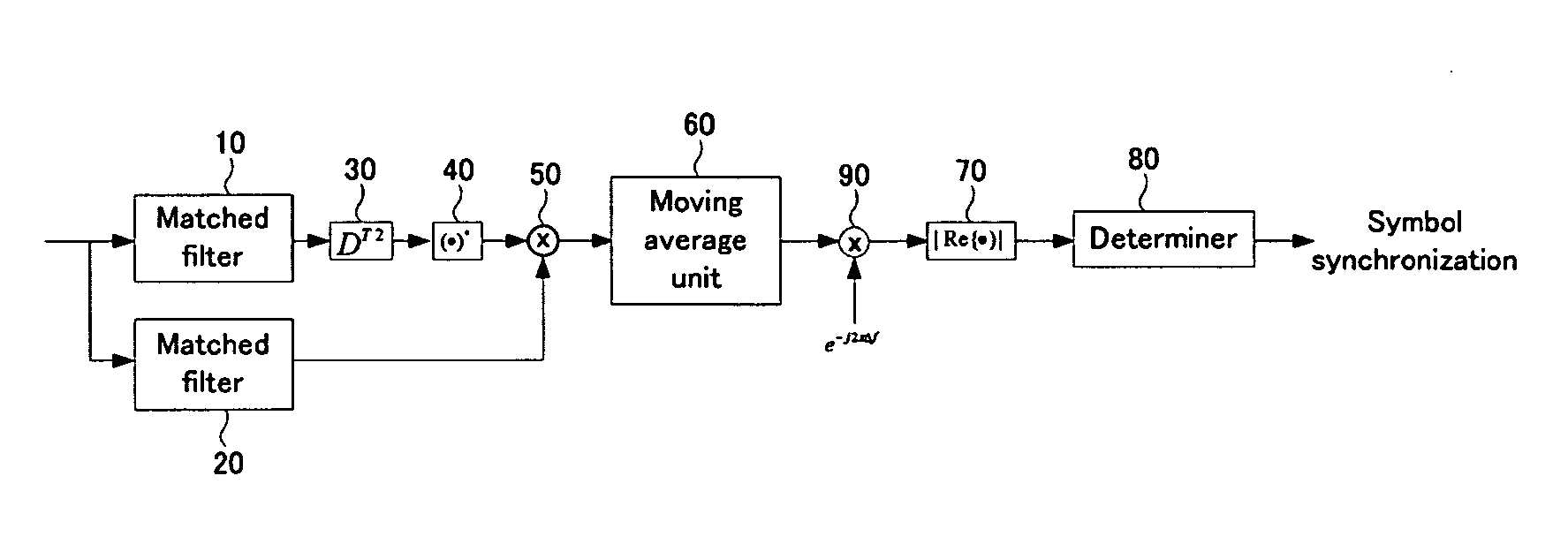
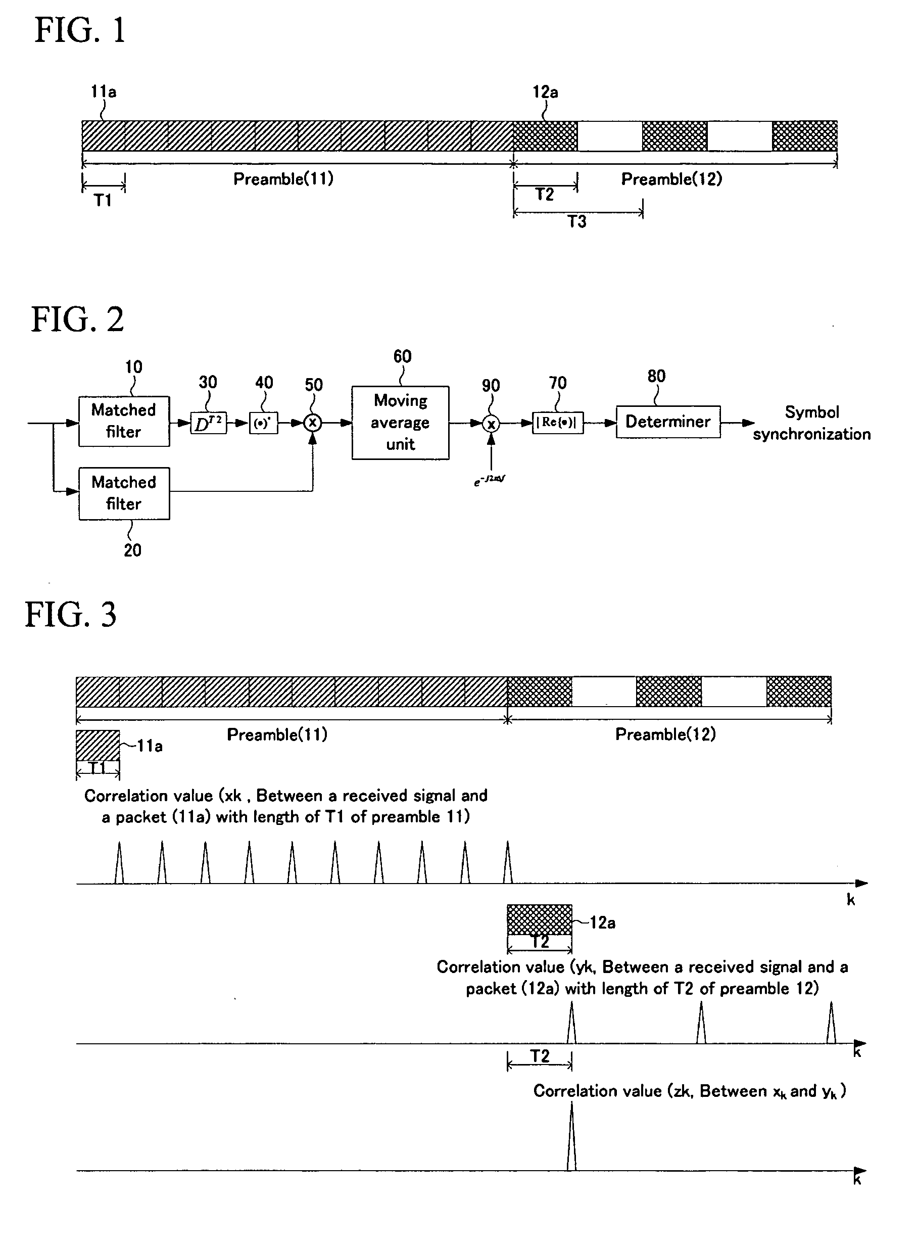
[0022] In FIG. 2, the symbol synchronization detecting apparatus includes matched filters 10 and 20, a delaying unit 30, a complex conjugator 40, a correlator 50, a moving average unit 60, a real number generator 70, and a determiner 80 according to the present invention. Herein, the moving average unit 60, the real number generator 70, and the determiner 80 are operated as a detector for detecting symbol synchronization in a correlation value of the correlator 50.

[0023] The matched filter 10 outputs a correlation value xk between a received signal rk and one period signal ak of the preamble 11 by multiplying a received signal rk by a matched filter coefficient. Herein, the matched filter coefficient corresponds to a value a*-k which is obtained by inverting an order of the one period signal ak of the preamble 11 on the time axis, and complex-conjugating the inverted order. In other words, an output xk of the matched filter 10 is given by Equation 1.

xk=rk*a−k  [Equation 1]

[0024] He...

second embodiment

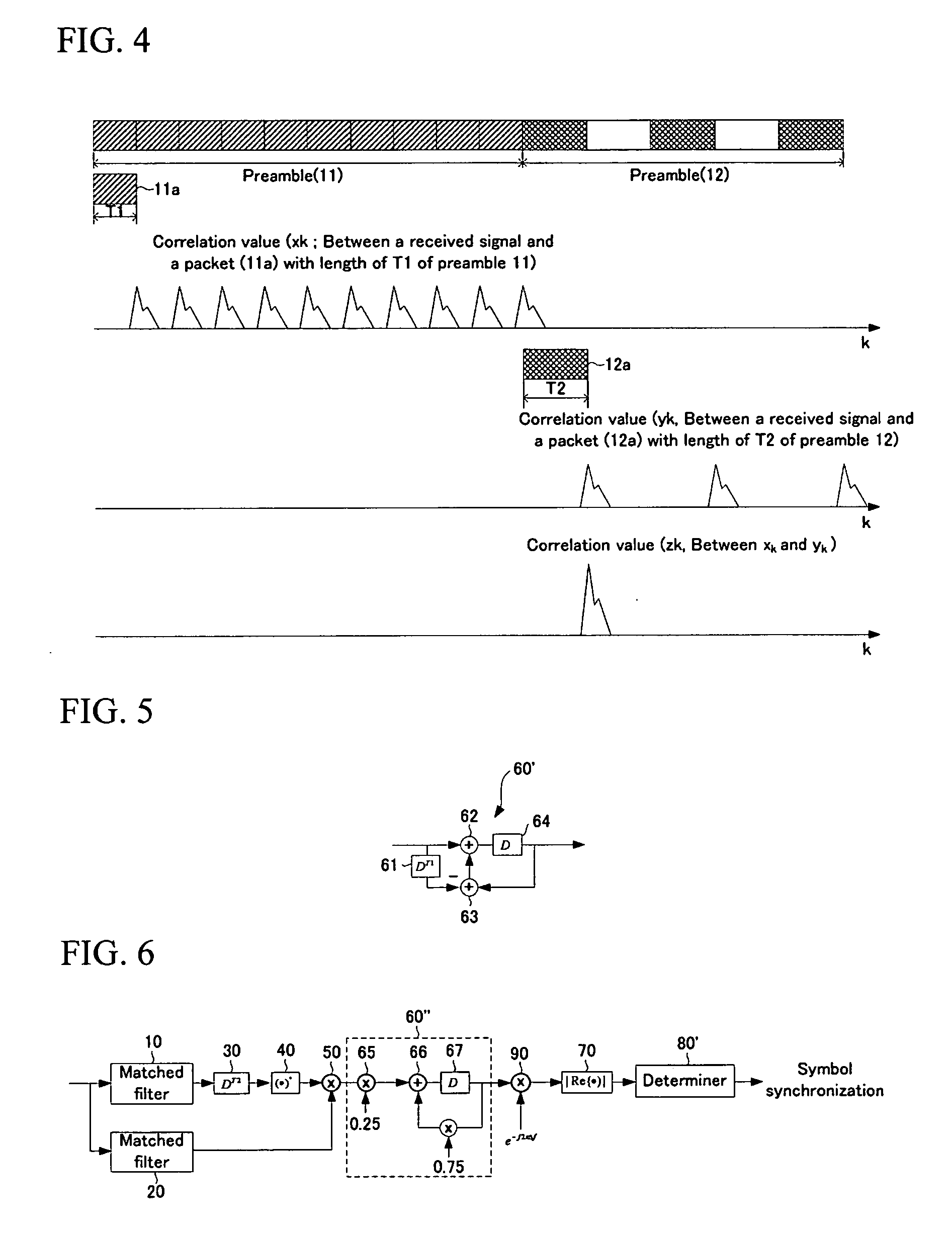
[0036] The symbol synchronization detecting apparatus of FIG. 2 requires (T1−1) number of delaying units (in this instance, registers) and (T1−1) number of adders to calculate a moving average value for a window with the size of T1. A method for reducing the number of adders in the symbol synchronization detecting apparatus of FIG. 2 will now be described with reference to FIG. 5. FIG. 5 is a schematic diagram of a moving average unit 60′ of a symbol synchronization detecting apparatus according to the present invention.

[0037] As shown in FIG. 5, the moving average unit 60′ includes delaying units 61 and 64, an adder 62, and a subtracter 63. The delaying unit 61 delays a correlation value zk by the length of T1 and outputs the delayed correlation value, and the subtracter 63 subtracts an output zk−T1 of the delaying unit 61 from an output of the moving average unit 60′. The output of the moving average unit 60′ corresponds to an output of the delaying unit 64. The adder 62 adds the ...


PUM


Abstract

An apparatus for detecting symbol synchronization in a received signal including a first preamble and a second preamble which is consecutive to the first preamble, the apparatus including a first correlator calculating a first correlation value between the received signal and a first pattern of a first period among iterative patterns of the first preamble, a second correlator calculating a second correlation value between the received signal and a second pattern of a second period among iterative patterns of the second preamble, a third correlator calculating a third correlation value between the first correlation value and the second correlation value, and a detector detecting symbol synchronization from the third correlation value.

Description

CROSS-REFERENCE TO RELATED APPLICATION [0001] This application claims priority to and the benefit of Korean Patent Application 10-2004-0104356 filed in the Korean Intellectual Property Office on Dec. 10, 2004, the entire content of which is incorporated herein by reference. BACKGROUND OF THE INVENTION [0002] (a) Field of the Invention [0003] The present invention relates to a packet communication system, and more particularly to a method for detecting symbol synchronization and an apparatus thereof in the packet communication system. [0004] (b) Description of the Related Art [0005] A method for detecting symbol synchronization that detects timing of a received packet, that is, a boundary between a preamble and a payload or a boundary between preambles in different patterns, is a very important technology in a packet-based transmission system. [0006] In particular, a symbol synchronization method is essential to find a start point of a Fast Fourier Transform (FFT) window for a modula...

Claims


Application Information

Patent Timeline
Patent Type & Authority Applications(United States)
IPC IPC(8): H04J3/06
CPCH04L27/2662H04L27/2675H04L7/02
Inventor JEON, TAEHYUNYU, HEEJUNGKIM, MYUNG-SOONCHOI, EUN-YOUNGLEE, SOK-KYULYU, DEUK-SU
Owner ELECTRONICS & TELECOMM RES INST
Why Eureka
Try Eureka