Tool coupler for connecting tool heads, such as drills, reamers, millers, turn-cutters, dies, and rams, to a tool holder

Active Publication Date: 2006-06-15
KENNAMETAL INC
View PDF29 Cites 11 Cited by
  • Summary
  • Abstract
  • Description
  • Claims
  • Application Information

AI Technical Summary

Benefits of technology

[0009] The problem is solved by means of a tool coupler according to at least one embodiment described herein, where, in accordance with the invention, the gripper groove is provided with two diametrically opposite blind bore holes with varying bore hole contours. In contrast with the solutions of the prior art, the diametrically opposite arrangement of the bore holes in the groove largely counteracts the unbalance. Additional bore holes for compensation of unbalance, which can weaken the body of the tool coupler, otherwise are not required, which advantageously simplifies the manufacture of such tool couplers.

Problems solved by technology

The unbalance resulting from the configuration manifests itself especially in tools rotating at high speed.
However, the tool carrier of EF 1 007 256 B1 is disadvantageous in that it matches only one certain machine tool type.
On the

Method used


Image

  • Tool coupler for connecting tool heads, such as drills, reamers, millers, turn-cutters, dies, and rams, to a tool holder
  • Tool coupler for connecting tool heads, such as drills, reamers, millers, turn-cutters, dies, and rams, to a tool holder
  • Tool coupler for connecting tool heads, such as drills, reamers, millers, turn-cutters, dies, and rams, to a tool holder

Examples


Example

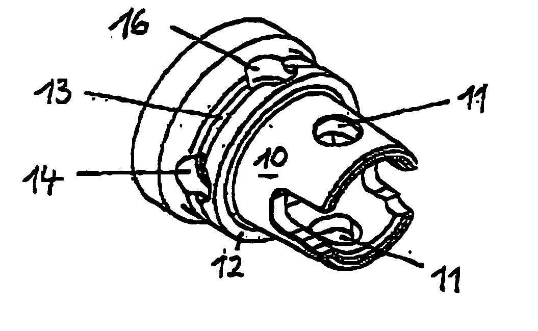
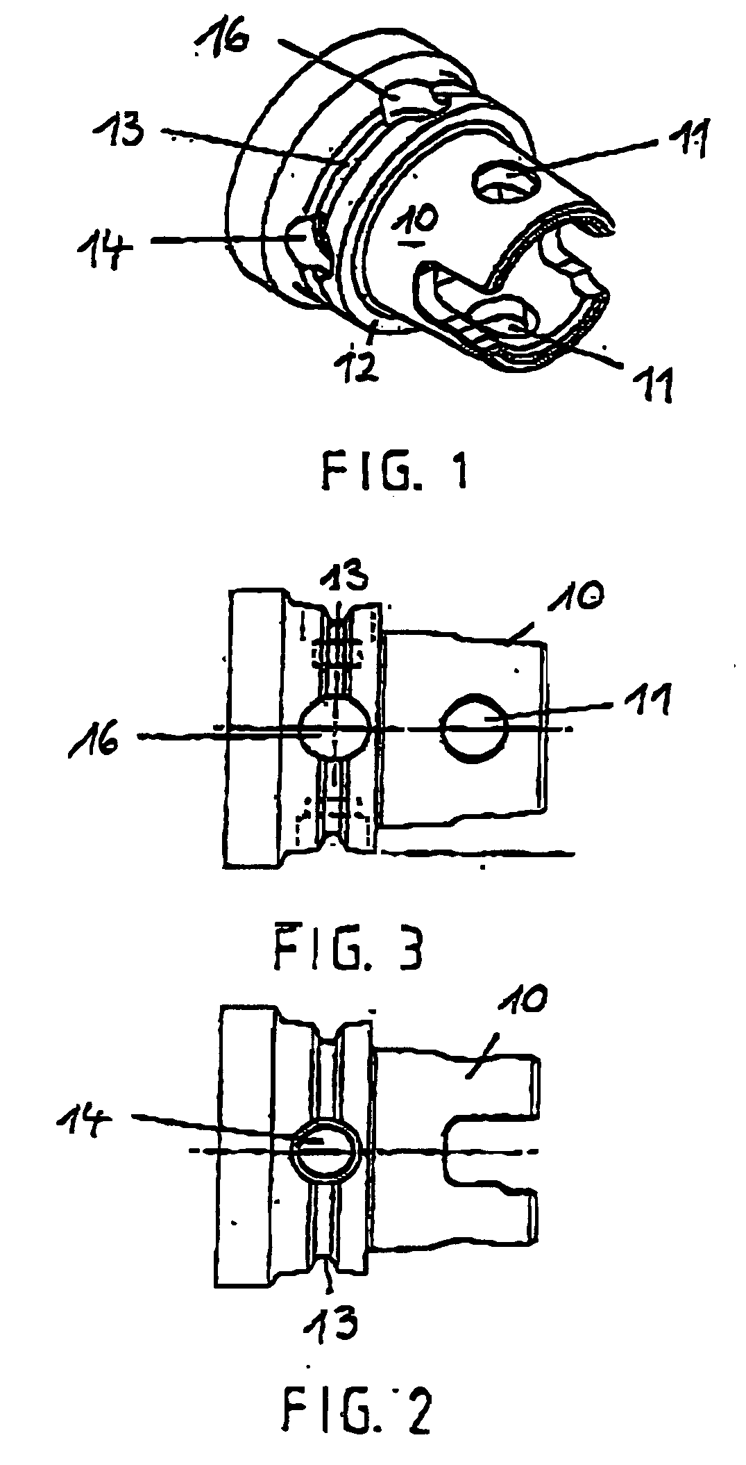
[0030] The tool coupler illustrated in FIG. 1 has a hollow shaft 10 with a conical outside surface provided with opposite openings 11 by means of which the tool coupler can be mounted in a machine spindle in connection with ball-shaped clamping elements (not shown). Furthermore, the tool coupler has a ring-shaped caller interacting with a correspondingly configured ring-shaped opposite surface of a basic holder on the machine tool. Tool couplers at this kind have been described in detail in EP 0 343 190 E1, for example, in addition, the tool coupler is provided with a substantially V-shaped continuous gripper groove 13 in which a gripping device (not shown) engages when the tool is replaced. On the side opposite the hollow shaft 10, the actual tool head is mounted for carrying the tool (not shown).

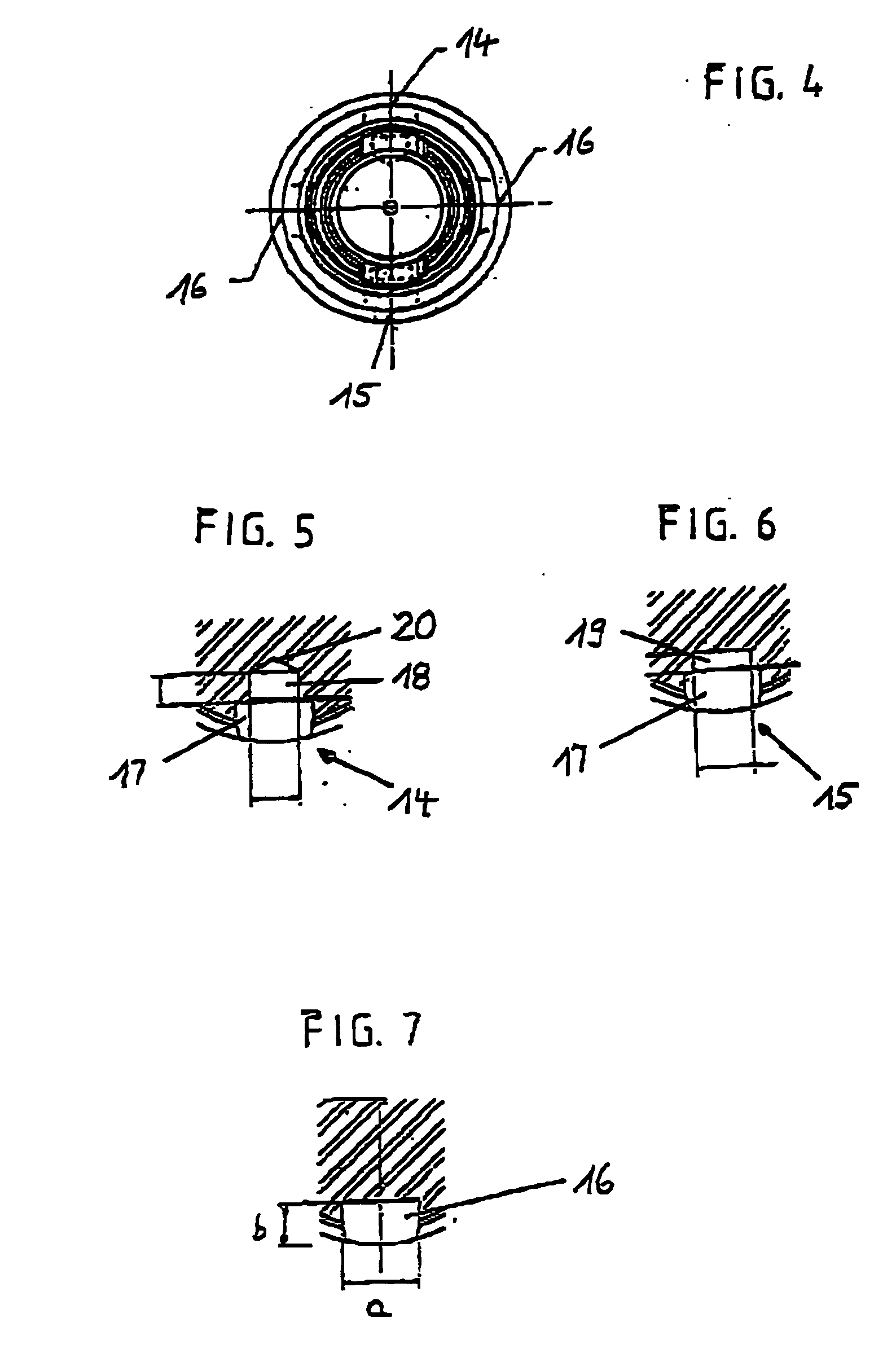
[0031] According to at least one possible embodiment, the tool coupler is first provided with two diametrically opposite blind bore holes 14 and 15 whose varying cross-sections are illust...


PUM

PropertyMeasurementUnit
Angleaaaaaaaaaa
Diameteraaaaaaaaaa
Diameteraaaaaaaaaa

Abstract

A tool coupler for connecting tool heads, such as drills, reamers, millers, turn-cutters, dies, and rams, to a tool holder. The tool coupler has a hollow shaft, a ring-shaped collar, and a gripper groove, in which gripper groove are disposed two diametrically opposite blind bore holes with varying bore hole contours. As stated in 37 C.F.R. §1.72(b): “A brief abstract of the technical disclosure in the specification must commence on a separate sheet, preferably following the claims, under the heading “Abstract of the Disclosure.” The purpose of the abstract is to enable the Patent and Trademark Office and the public generally to determine quickly from a cursory inspection the nature and gist of the technical disclosure. The abstract shall not be used for interpreting the scope of the claims.” Therefore, any statements made relating to the abstract are not intended to limit the claims in any manner and should not be interpreted as limiting the claims in any manner.

Description

CONTINUING APPLICATION DATA [0001] This application is a Continuation-In-Part application of International Patent Application No. PCT / EP2004 / 007279, filed on Jul. 3, 2004, which claims priority from Federal Republic of Germany Patent Application No. 103 36 869.8, filed on Aug. 11, 2003. International Patent Application No. PCT / EP2004 / 007279 was pending as of the filing date of this application. The United States was an elected state in International Patent Application No. PCT / EP2004 / 007279.BACKGROUND [0002] 1. Technical Field [0003] The application generally relates to a tool coupler for connecting tool heads, such as drills, reamers, millers, turn-cutters, dies, and rams, to a tool holder. The application further relates to a tool coupler for connecting a replaceable tool head to a machine tool comprising an at least partly or fully conical or cylindrical hollow shaft and a ring-shaped collar interacting with a correspondingly configured receiving bore hole and a ring-shaped opposi...

Claims


Application Information

Patent Timeline
IPC IPC(8): B23C5/00B23B31/00B23Q3/157
CPCB23B31/006B23B2231/0292B23B2231/10Y10T409/309408B23B2250/16Y10T409/30952Y10T483/134B23B2250/04
Inventor STORCH, HELMUTERICKSON, ROBERT A.
Owner KENNAMETAL INC
Why Eureka
Try Eureka