Airfoil platform impingement cooling

a technology of airfoil platform and impingement, which is applied in the direction of liquid fuel engine, motor, engine fuction, etc., can solve the problems of increased turbine vane manufacturing cost and additional cooling air

Active Publication Date: 2006-06-15
PRATT & WHITNEY CANADA CORP
View PDF18 Cites 31 Cited by
  • Summary
  • Abstract
  • Description
  • Claims
  • Application Information

AI Technical Summary

Benefits of technology

[0013]FIG. 3 is a schematic cross-sectional side view of a high pressure turbine section of the gas turbine engine shown in FIG. 2, illustrating a vane platform impingement cooling scheme in accordance with an embodiment of the present invention.

Problems solved by technology

One disadvantage of the above vane cooling scheme is that it requires additional cooling air to purge the turbine cavity between the adjacent rows of vanes and turbine blades.
Furthermore, the film cooling holes must be sufficiently long to allow the cooling air to flow from the plenum to the gas path side of the platform, which results in greater turbine vane manufacturing costs.

Method used


Image

  • Airfoil platform impingement cooling
  • Airfoil platform impingement cooling
  • Airfoil platform impingement cooling

Examples


Embodiment Construction

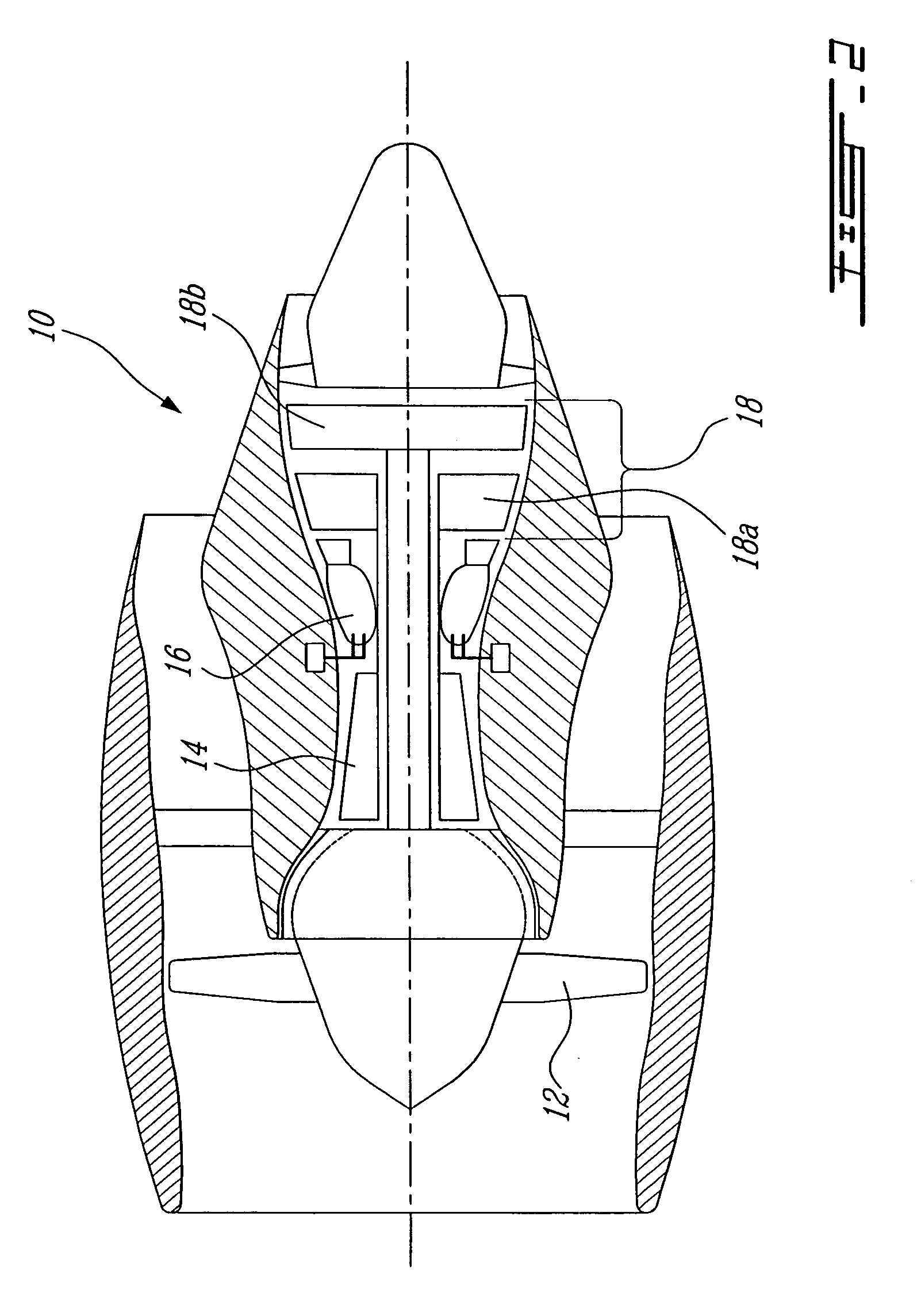
[0014]FIG. 2 illustrates a gas turbine engine 10 of a type preferably provided for use in subsonic flight, generally comprising in serial flow communication a fan 12 through which ambient air is propelled, a multistage compressor 14 for pressurizing the air, a combustor 16 in which the compressed air is mixed with fuel and ignited for generating an annular stream of hot combustion gases, and a turbine section 18 for extracting energy from the combustion gases.

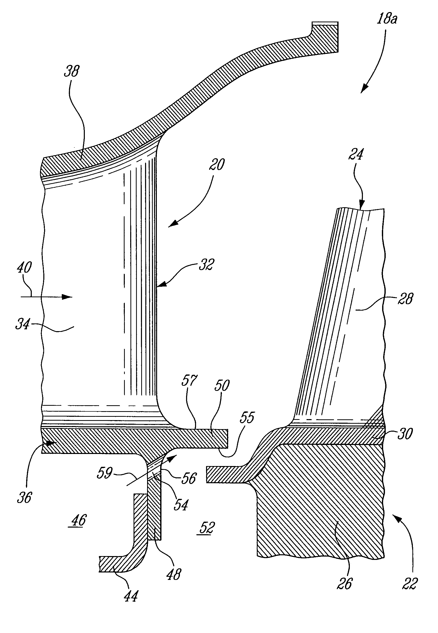
[0015] The turbine section 18 typically comprises a high pressure turbine 18a and a low pressure turbine 18b downstream of the high pressure turbine 18a. As shown in FIG. 3, the high pressure turbine 18a includes at least one turbine nozzle 20 and one turbine rotor 22. The turbine nozzle 20 is, configured to optimally direct the high pressure gases from the combustor 16 to the turbine rotor 22, as well know in the art.

[0016] The turbine rotor 22 includes a plurality of circumferentially spaced-apart blades 24 (only one shown ...


PUM


Abstract

A gas turbine engine airfoil has a platform cooling scheme including an impingement hole for directing cooling air against an undersurface of the airfoil platform.

Description

TECHNICAL FIELD [0001] The invention relates generally to gas turbine engines and, more particularly, to airfoil platform impingement cooling. BACKGROUND OF THE ART [0002] Gas turbine engine airfoils, such as high pressure turbine vanes, are typically cooled by compressor bleed air. Conventional turbine vanes, such as the one shown at 9 in FIG. 1, generally have a radially inner band or platform 11 and a plenum 13 defined below the platform 11 for receiving the compressor bleed air. Film cooling holes 15 typically extend from the underside of the platform 11 to the platform radially outer surface 17 (i.e. the platform surface facing the hot gas stream). The air flowing from the holes 15 forms a thin cooling film on the radially outer surface 17 of the platform 11. [0003] One disadvantage of the above vane cooling scheme is that it requires additional cooling air to purge the turbine cavity between the adjacent rows of vanes and turbine blades. Furthermore, the film cooling holes mus...

Claims


Application Information

Patent Timeline
Patent Type & Authority Applications(United States)
IPC IPC(8): F04D31/00
CPCF01D5/081F01D5/147F01D25/12F05D2240/81F05D2260/201
Inventor DUROCHER, ERICSYNNOTT, REMYBLAIS, DANY
Owner PRATT & WHITNEY CANADA CORP
Why Eureka
Try Eureka